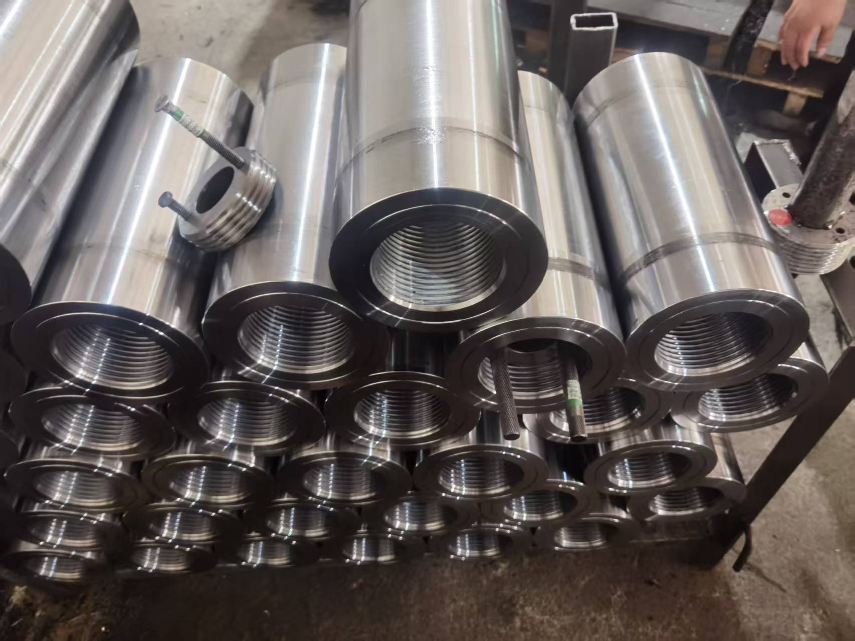
A purchase order for a “32 mm coupler” is missing a critical detail: which bar it must connect.
Take two catalogue entries for a 1¼-inch, nominally 32 mm bar. DYWIDAG lists a Grade 150 coupler 171 mm long, with a 60 mm outside diameter. Williams lists its R72-10 stop-type coupling at 114 mm long and 54 mm outside diameter. Both belong to 150 ksi product families. Yet the sleeves are plainly different. 1 2
For engineers and purchasers specifying post-tensioning bar couplers, the order needs to identify the bar, mating thread, engagement at each end and material condition. The test report must cover that combination. Screwing the parts together checks assembly fit. Load capacity has to be established for the complete joint.
Follow the force through a post-tensioning bar coupler
A coupler transfers axial tension from one bar’s engaged thread into the sleeve, then through the thread engagement with the second bar. Most of the working surfaces disappear from view once the joint is assembled.
The Post-Tensioning Institute’s December 2024 addendum to PTI/ASBI M50.3-19 identifies four variables in bar–nut and bar–coupler connections: thread type, engagement length, dimensional tolerances and material strength. Its commentary describes rational analysis verified by a small test series. These are the details the drawing and test report have to address. 3
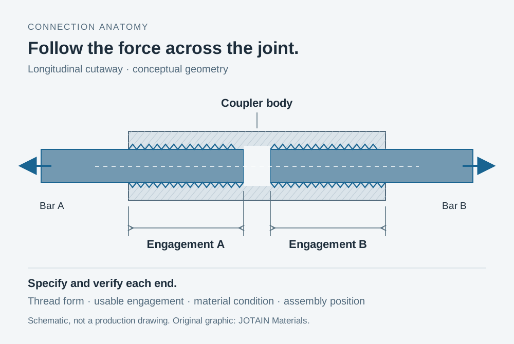
Start with the bar and sleeve drawings side by side. Check the mating thread, usable threaded length and final assembly position against both drawing revisions. A sleeve drawing alone leaves half the connection unresolved.
The word “coupler” also covers structural tie-rod connectors and reinforcing-bar splices. Their specifications and approval routes differ from those for prestressing-bar connections. The distinction is covered in our comparison of PT bars, rebar and tie rods.
Two 32 mm designations, two different sleeves
Here are the published dimensions for the two products:
| Published product | Listed bar designation | Overall coupler length | Outside diameter |
|---|---|---|---|
| DYWIDAG Grade 150 THREADBAR hardware | 1¼ in / 32 mm | 171 mm | 60 mm |
| Williams R72-10 stop-type coupling, 150 ksi All-Thread-Bar | 1¼ in / 32 mm | 114 mm | 54 mm |
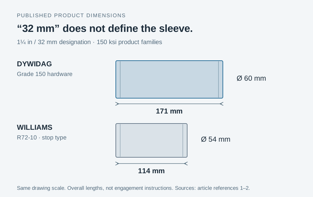
Carry the full product designation into the enquiry and purchase order. The mating bar, controlled drawing and required test basis should be settled before prices are compared. Otherwise, two quotations headed “32 mm coupler” may be pricing different components.
Nor can engagement be calculated by halving the catalogue length. The entry, thread termination and any internal stop affect how much complete thread is available. Read the required engagement from the component and assembly details.
Engagement is an assembly condition
Williams offers tap-through and stop-type couplings, describing the stop type as ensuring 50:50 engagement. DYWIDAG notes that its couplers are not necessarily intended to thread all the way through. Each arrangement needs its own assembly instructions. 1 2
Once the thread is hidden, how does the person assembling the joint know that both bars are in the right position?
The approved procedure must answer that question. Depending on the design, it may use a stop, an insertion-depth reference or an inspection feature. Specify the position at both ends and the means of checking it. An instruction to “fully engage” the bar is incomplete without that reference.
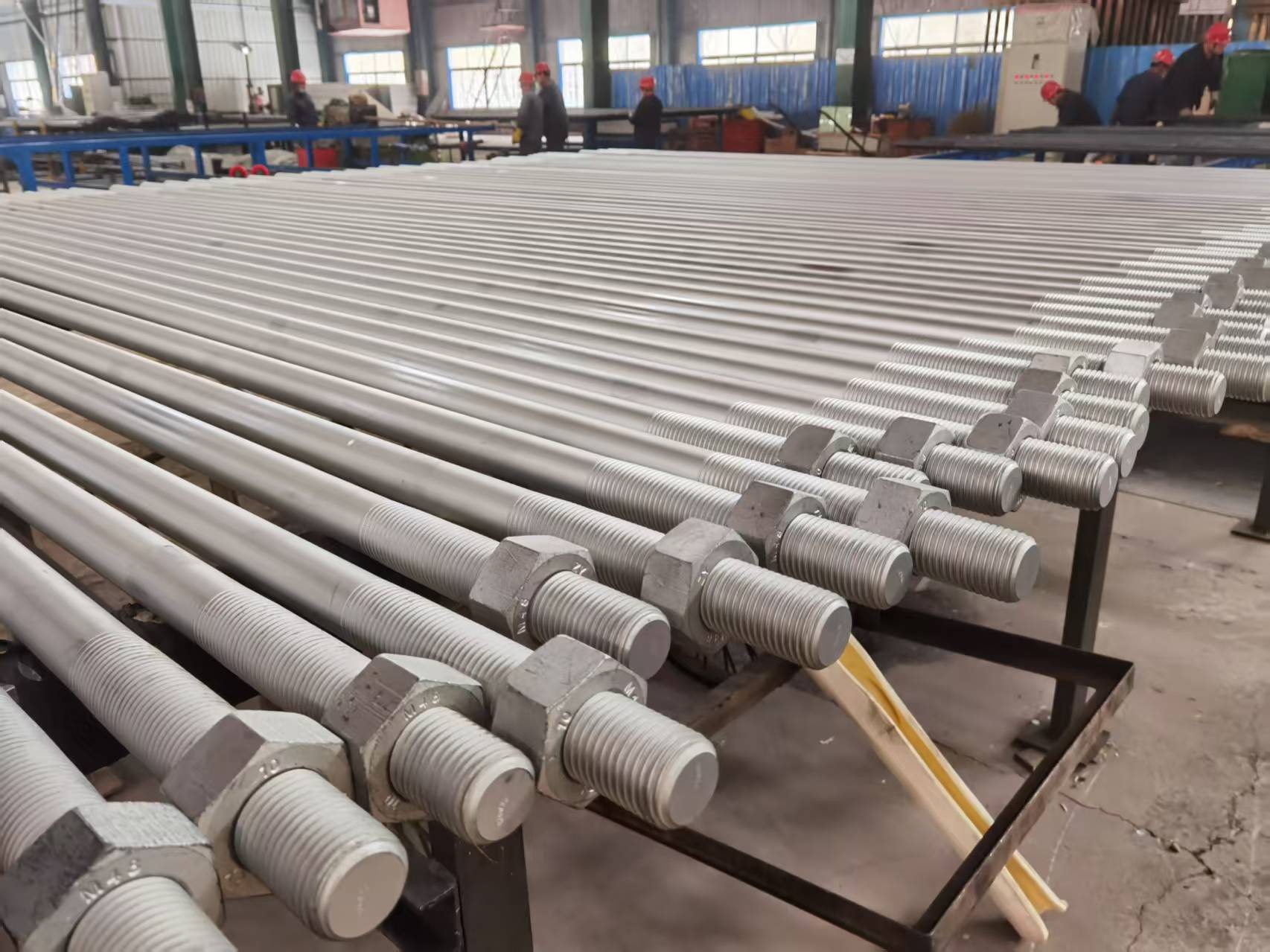
Inspect the finished thread with the gauges and dimensional checks specified for that thread system. Trial assembly can reveal a fit problem, but it cannot establish tensile capacity. The inspection plan must identify the dimensions and surfaces on which the accepted design depends.
Record the component identity, drawing revision, inspection method, result and disposition. That is enough to make a dimensional check traceable without burying it in paperwork.
Keep production tied to the tested design
A connection test covers the parts placed in the rig. Production must preserve the material, geometry and processing conditions on which that result depends.
ASTM A722/A722M-26 covers Type I and Type II high-strength bars for prestressed concrete and ground anchors, with a minimum tensile-strength level of 150,000 psi [1035 MPa]. ISO 6934-5:2024 specifies high-tensile prestressing bars with plain or threaded surfaces. Both address the bar. The sleeve and assembled connection need their own specification and acceptance basis. 4 5
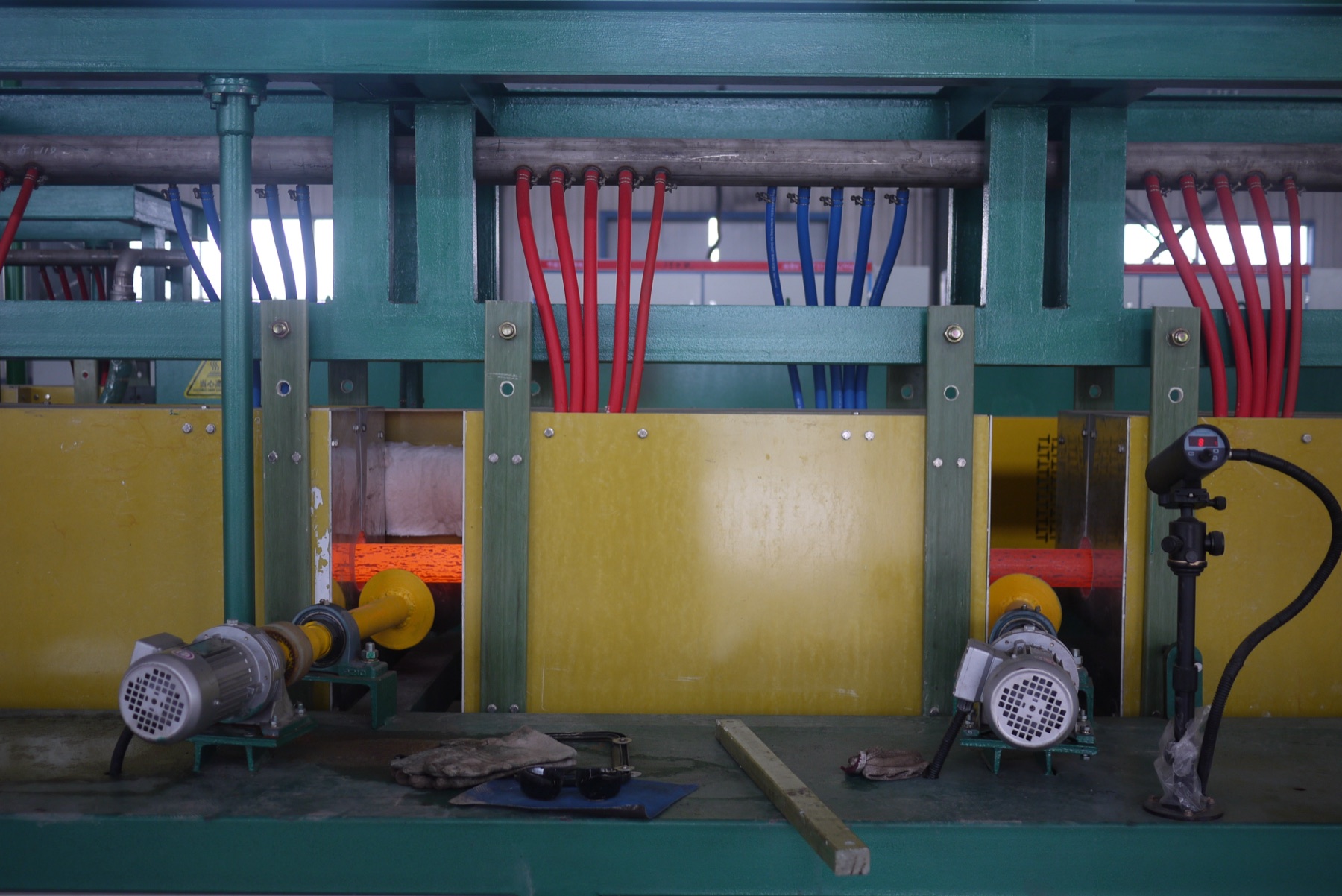
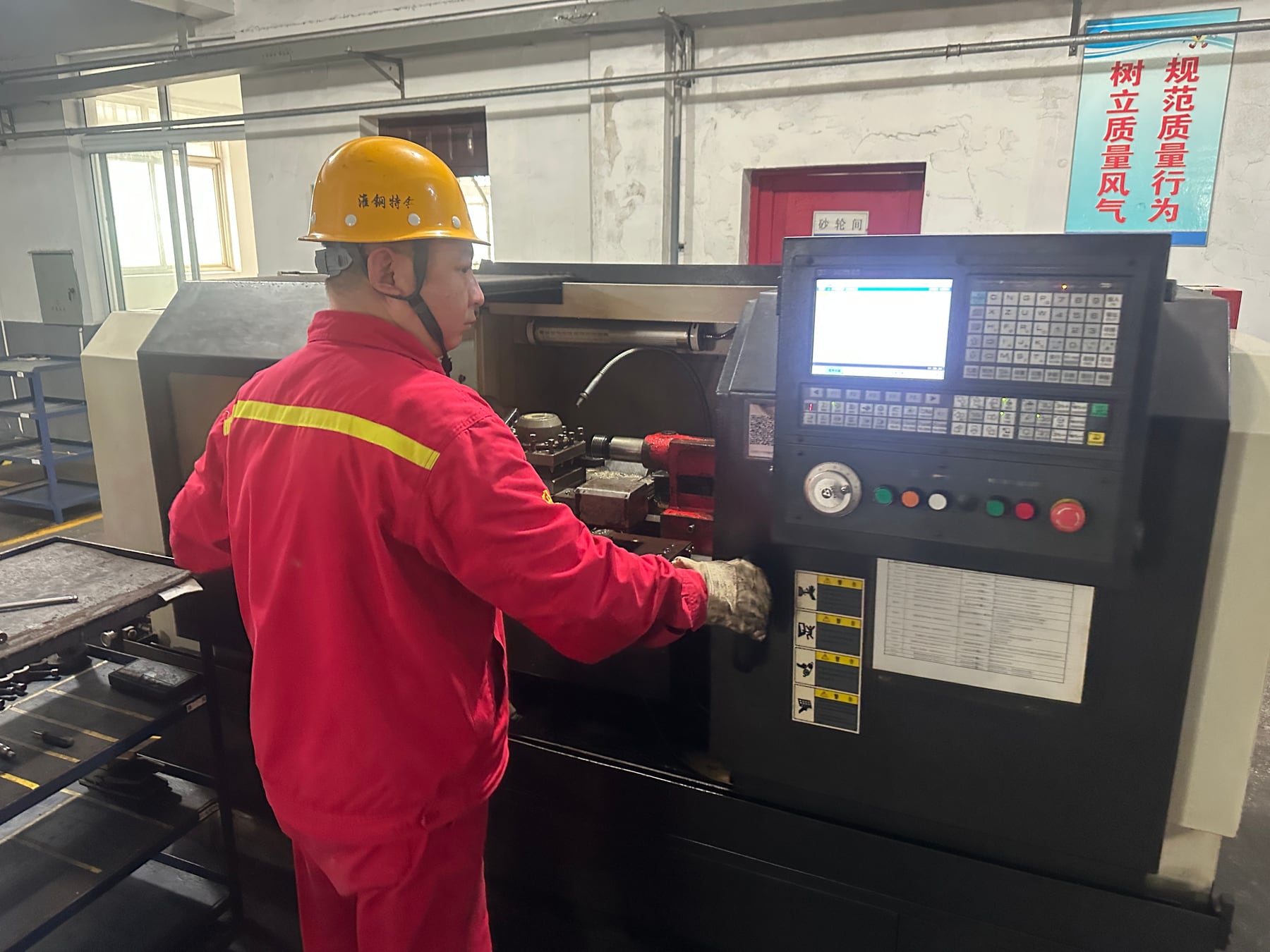
Follow the production route from incoming steel through heat treatment, machining or thread forming, surface treatment and final inspection. Establish when the thread is checked. If another operation subsequently changes a functional surface, the inspection plan must cover the finished condition.
Coating belongs in this review. DYWIDAG’s hardware sheet gives dimensions for uncoated bars and directs questions about coated bars or oversize hardware to its engineers. Specify the protection system before the hardware is ordered. 1
At JOTAIN, we start a bar or machined-component enquiry with the mating drawings, material condition, processing scope and inspection requirements. We also establish what is being delivered: bar stock, a heat-treated blank or a finished component. Our PT bars and machined couplers page sets out the information needed for that review. 11
The thread-making route is covered separately in thread rolling versus machining. Whichever route is used, acceptance applies to the finished part.
Which report proves what?
A material certificate, a dimensional report and a connection test are different records. Read each for the question it can actually answer.
What is the steel?
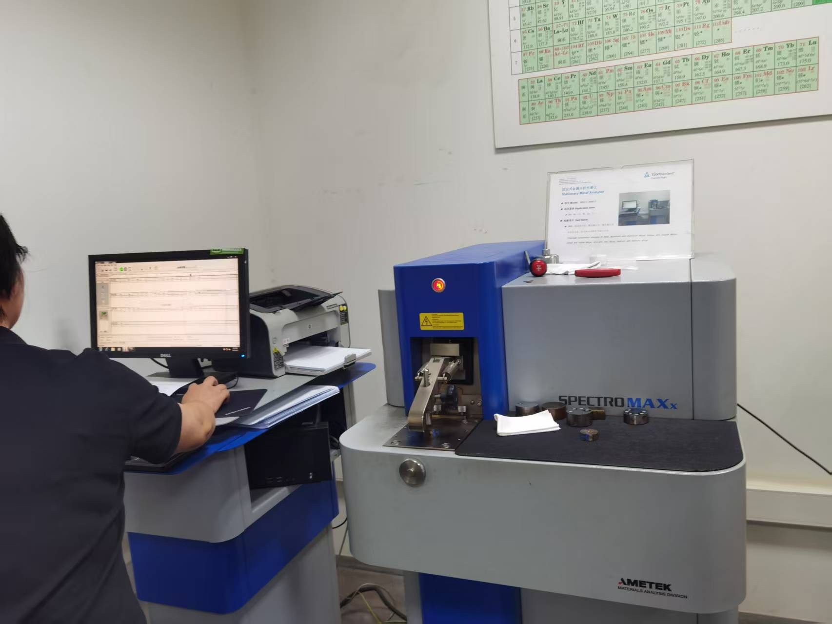
A material certificate reports chemistry and mechanical properties for an identified heat or lot. Check the specimen location, product condition and applicable standard. ISO 15630-3:2025 covers test methods for prestressing bar, wire and strand, while leaving sampling conditions to the product standards. The inspection plan needs both the test method and the sampling basis. 6
Does the manufactured geometry match?
A dimensional report should identify the finished features inspected, the mating-part reference and the inspection stage. Measurements taken on a blank do not accept the thread subsequently machined into it.
When a drawing changes, record the affected dimensions and interfaces, and who accepted the revision. Check whether earlier inspection or test results still apply before carrying them into the new order.
How does the assembly behave under load?
PTI’s Technical Manual for PT Systems Qualification Testing and Certification, G3-0323, Section 2.4, requires high-strength bar couplers to develop 100% of the bar’s specified tensile strength when tested unbonded, supported by written certification. Its checklist also asks whether the material properties and dimensions on system drawings agree with those used in testing. 7
For production, the crucial check is whether the tested parts match the parts on the current drawing.
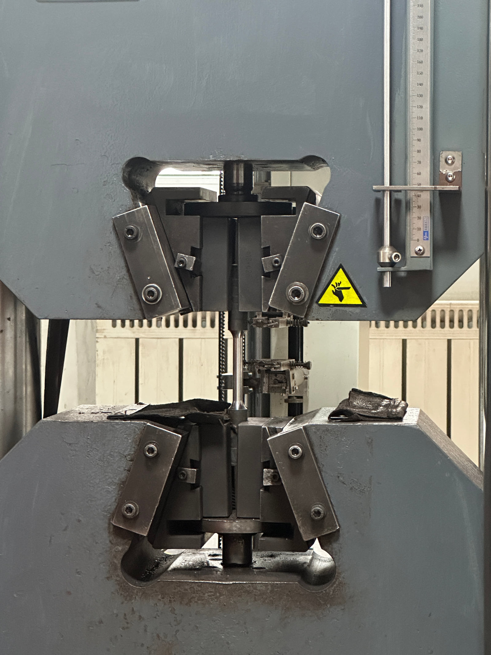
Acceptance percentages also need careful reading. EAD 160004-00-0301, Section 2.2.1, sets static-test criteria against both actual and specified characteristic tensile-element strength, together with elongation, failure-mode and movement requirements. Those criteria cannot be reduced to a percentage and treated as interchangeable with PTI's requirement. 8
Name the applicable system, assessment or project specification and its acceptance clause in the inspection plan. “Tested to destruction” is not an acceptance criterion.
What does “two million cycles” mean?
Two million cycles at what load? Without the upper load and the lower load or stress range, a cycle count says little about the severity of a fatigue test.
EAD 160004-00-0301, Section 2.2.2, specifies 2 million cycles, a minimum stress range of 80 MPa, and maximum stress of 65% of the tensile element’s characteristic strength. The procedure also addresses component failure, tensile-element damage and stabilization of relative movement. All of those conditions belong with the reported result. 8
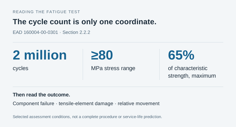
Macalloy, for example, reports that its fully threaded, 32 mm S1030 stainless bar completed two million cycles at an 80 MPa stress range, with static tests before and after cycling. The result belongs to that identified bar product. It does not qualify a different bar–coupler assembly. 9
Before accepting a report marked “passed”, locate the specimen drawing, material identity, assembly arrangement and loading conditions. Match them to the ordered product, then read the recorded outcome. The cycle count is a laboratory result, not a service-life forecast.
Fatigue is also distinct from PT-bar relaxation: one concerns repeated loading, the other force loss under the specified constraint over time. A specification can require both.
Leave room for the coupler inside the duct
The sleeve's outside diameter matters when the tendon enclosure is detailed. There must be room for the coupler, its specified movement and the protection arrangement.
The Federal Highway Administration’s 2013 Post-Tensioning Tendon Installation and Grouting Manual, Section 2.3.1.2, gives guidance for single-bar tendons: the internal duct diameter should exceed the maximum outside dimension of the bar or coupler by at least 12 mm, with more clearance potentially needed for the application. The reference dimension is the largest component, not merely the nominal bar size. 10
PTI’s bar-coupler qualification checklist asks about enclosure movement and grout access to all coupler components. Check where the sleeve sits, how far the assembly moves, and how the enclosure will be filled and sealed. Resolve these details before releasing the hardware for manufacture. 7
The steel sleeve transfers force between the bars. The enclosure provides the specified protection environment. The assembled detail has to accommodate both functions.
What should arrive with the components?
Start with a marked component or packing record. Can the buyer find its drawing revision, material record and inspection results without reconstructing the order from email? That is a practical test of the delivery paperwork.
Use this review sheet alongside the purchase order and approved system requirements:
| Record | Question it should answer |
|---|---|
| Bar and coupler drawing revisions | Are these the mating components that were ordered? |
| Material and processing records | Which heats, lots and finished conditions do they represent? |
| Thread and dimensional inspection | Which features were checked, by what method and at what production stage? |
| Assembly qualification reference | Which combination and loading conditions were tested or otherwise assessed? |
| Engagement and assembly procedure | How is the specified engagement verified at each end? |
| Protection and packing record | How are the accepted threads and surfaces protected through delivery? |
Use the same list when preparing an enquiry. Send the mating-bar and sleeve drawings, material condition, quantity, destination and inspection scope. These give the manufacturer a defined job to assess and quote. 11
Before you order
Can a PT bar and coupler from different manufacturers be mixed?
Only where the proposed combination is covered by the required compatibility review and approval. Matching nominal sizes and a successful trial fit are insufficient. Check the thread geometry, materials, engagement and assembly-performance basis with the specified system provider and project approver before ordering.
How much thread engagement does a coupler need?
Use the engagement specified for that bar–coupler assembly. Overall sleeve length, or half that length, is not a substitute. The drawing and assembly procedure should identify the usable engagement required at each end and the method for checking it after assembly.
Is a material certificate enough to accept the connection?
No. It reports the identified material's chemistry and mechanical properties. Accepting the connection also requires the specified dimensional checks and assembly-performance records. Each record must identify the relevant part or assembly, drawing revision, test conditions and acceptance basis.
Does a fatigue result replace a relaxation result?
No. Fatigue concerns repeated loading; relaxation concerns force loss under the specified constraint over time. A PT-bar specification can require both, alongside tensile properties and connection tests. Each result has to meet its own test method and acceptance criterion.
Specify the connection, not just the diameter
The difference between a 171 mm sleeve and a 114 mm sleeve is easy to spot. Differences in thread geometry, usable engagement and processing condition take more work to establish. They need to be settled before a purchase order for post-tensioning bar couplers is placed.
Send the bar and sleeve drawings together. Agree the finished condition, inspection scope and qualification basis in writing. At delivery, the part in the crate should be the part on the drawing—and the one covered by the acceptance records.
Bring the connection drawing to the manufacturer
JOTAIN manufactures drawing-based steel components and provides bar supply, heat treatment, threading and machining. Send both mating drawings and the required inspection scope for a technical quotation.
Discuss PT bars and machined couplersReferences
- DYWIDAG — Post-Tensioning THREADBAR Technical Specification. Public two-page data sheet, file labelled October 2024; Grade 150 properties on PDF page 1 and hardware dimensions/notes on page 2. Product-specific published dimensions.
- Williams Form Engineering — Tie Rod Connectors. “Stop Type Couplings”; R72-10 row for 150 ksi All-Thread-Bar. Manufacturer product data and stop-type description.
- Post-Tensioning Institute — PTI/ASBI M50.3-19, Addendum 1, December 2024. Page 5: commentary on bar–anchor-nut and bar–coupler connection performance.
- ASTM A722/A722M-26 — High-Strength Steel Bars for Prestressed Concrete. Official public scope, Sections 1.1 and 1.5; current listed edition checked October 10, 2026.
- ISO 6934-5:2024 — Steel for the prestressing of concrete, Part 5. Official scope and edition: high-tensile bars with plain or threaded surfaces.
- ISO 15630-3:2025 — Steel for the reinforcement and prestressing of concrete, Test methods, Part 3. Official public scope; test-method and sampling distinction.
- Post-Tensioning Institute — Technical Manual for PT Systems Qualification Testing and Certification, PTI-CRT70 G3-0323. Section 2.4, printed page 9 / PDF page 11: PT bar couplers.
- European Organisation for Technical Assessment — EAD 160004-00-0301. Sections 2.2.1–2.2.2, pages 22–24; Annex C.3, pages 80–81. Consult the applicable assessment and complete procedure for qualification.
- Macalloy — Post Tensioning, “Fatigue Properties in the S1030”. Manufacturer-reported result for the fully threaded 32 mm S1030 product. Public page checked October 10, 2026.
- Federal Highway Administration — Post-Tensioning Tendon Installation and Grouting Manual. Version 2.0, May 2013; Section 2.3.1.2, printed page 2-9 / PDF page 59.
- JOTAIN Materials — Post-tensioning bars and machined couplers. Published product and processing scope; drawing and inspection inputs.
Technical sources checked October 10, 2026. Photographs: JOTAIN Materials. Explanatory graphics: JOTAIN Materials. Published product dimensions and reported test results retain their original manufacturer and product attribution. Questions or corrections: [email protected].