
A 4140 or 42CrMo4 bar can meet its incoming hardness and straightness requirements yet change shape when machined. Removing metal can redistribute existing residual stress; cutting can introduce new near-surface stress; and a part machined while elastically deflected can spring back after release. Temperature and the inspection setup can also change the result you see. These mechanisms require different corrective actions. Aurrekoetxea et al., 2020; Zielinski et al., 2021; Beekhuis et al., 2009.
Control distortion by matching the supplied condition, stock-removal sequence, workholding and inspection plan to the finished component.
For shafts, pins and other alloy-steel components, start with the exact grade standard, delivery condition, section size and required properties. The same machining questions arise with both 4140 and 42CrMo4, while their order specifications must be checked separately. Ovako’s 42CrMo4 material data illustrates the differences between grade variants and section sizes. 42CrMo4 material data.
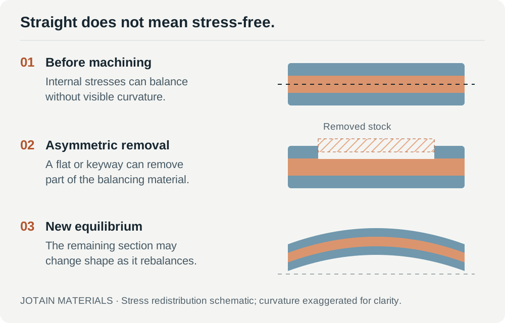
Figure 1 — Material removal changes the stress balance.
Swipe across the image to inspect its panels, or select it for the full-size original.
Removing material changes the balance of the stresses in the remaining section.
Select an image to open the full-size original and inspect its labels.
Key takeaways
- Material removal redistributes residual stress.
- A smaller diameter sharply reduces bending stiffness.
- Measure the released part after roughing and before finishing.
1. Residual stress in a straight bar
Residual stresses remain within a component after the external loading or temperature differences that produced them have gone. They can balance internally without an obvious bend. Thermal, transformation-related and non-uniform plastic deformation histories all matter. A hardness result does not describe that internal stress field. 1
When machining removes part of a stressed section, the remaining material finds a new equilibrium. Asymmetric removal can produce bending or twisting; symmetric removal from an ideally symmetric stress field can change dimensions while preserving straightness. Aurrekoetxea and colleagues examine this redistribution mechanism through layer-removal experiments on aluminium plate. 13
For an investigation, obtain the actual route: supplied condition, heat-treatment history, straightening history, bar orientation and machining sequence. Record what changed between the last acceptable measurement and the first unacceptable one. A batch hardness certificate is useful evidence, but it cannot answer that sequence of questions on its own.
For the metallurgical background, see Steel Heat Treatment: Microstructure, Hardness and Toughness.
2. First identify what “bending” actually means
Do not treat every indicator movement as the same defect. Centreline straightness, roundness, cylindricity and run-out describe different characteristics. A rotating indicator reading is not automatically a measurement of centreline straightness; its interpretation depends on the specified feature, datum and setup. Use the drawing's geometrical requirement and an agreed inspection method. ISO 1101:2017
Match the observation to a controlled comparison:
| What you observe | What to investigate | A useful comparison |
|---|---|---|
| Shape changes immediately after unclamping | Workholding deformation, support loads and residual-stress redistribution | Record the part in the fixture and again on the agreed released-part support arrangement. |
| Bow appears after a keyway, flat or eccentric feature | Asymmetric removal, reduced stiffness and changed stress balance | Measure immediately before and after that operation; preserve angular orientation. |
| Size or shape readings change as the part cools | Workpiece temperature, temperature gradients and measurement conditions | Recheck after thermal equilibration using the same datum and supports. |
| The result changes with insert condition or cutting sequence | Cutting forces, tool condition, heat input and surface integrity | Compare controlled trials with material identity, geometry and measurement method held consistent. |
| A disagreement appears only between inspection setups | Datum selection, support span, alignment and gravity sensitivity | Reproduce one documented setup before judging material conformity. |
Beekhuis and colleagues studied chuck deformation and cutting effects in thin-walled bearing rings. Their work shows why the clamped shape and the released shape belong in separate inspection records. Beekhuis et al., 2009
Measure before and after the operation where movement first appears, using the same datum, supports and temperature condition.
3. Stock removal changes stiffness as well as stress
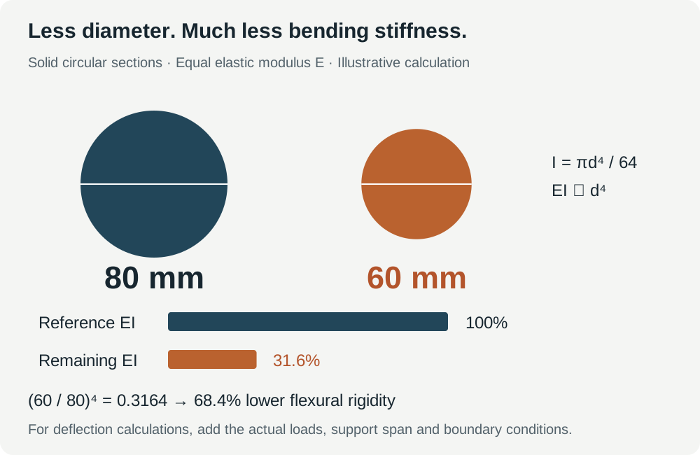
Long unsupported spans, small remaining diameters, thin walls and asymmetric features deserve early attention. There is a simple geometric reason: for a solid circular section, the second moment of area is I = πd⁴ / 64. At the same elastic modulus, flexural rigidity EI therefore scales with the fourth power of diameter. MIT, moment of inertia of beam cross sections
For a solid bar reduced from 80 mm to 60 mm diameter, the remaining flexural rigidity is (60 / 80)⁴ = 0.3164, or 31.6% of the original value at equal elastic modulus. A 25% reduction in diameter therefore removes 68.4% of the bending stiffness.
Figure 2 — Diameter and bending stiffness do not fall at the same rate.
Swipe across the image to inspect its panels, or select it for the full-size original.
At equal elastic modulus, a 60 mm solid bar retains 31.6% of the bending stiffness of an 80 mm bar.
Select an image to open the full-size original and inspect its labels.
This comparison explains why a setup that is adequate for the starting blank may not suit the nearly finished shaft. Review support and workholding at the weakest process stage—not only at the incoming diameter. For non-circular or hollow sections, calculate the actual section properties rather than applying the solid-bar ratio.
Keep machining stock purposeful: enough for the agreed downstream operations and correction route, but justified by the geometry and process. Our machining-allowance guide covers the information needed to define that allowance.
4. Cutting forces and residual stress in 42CrMo4
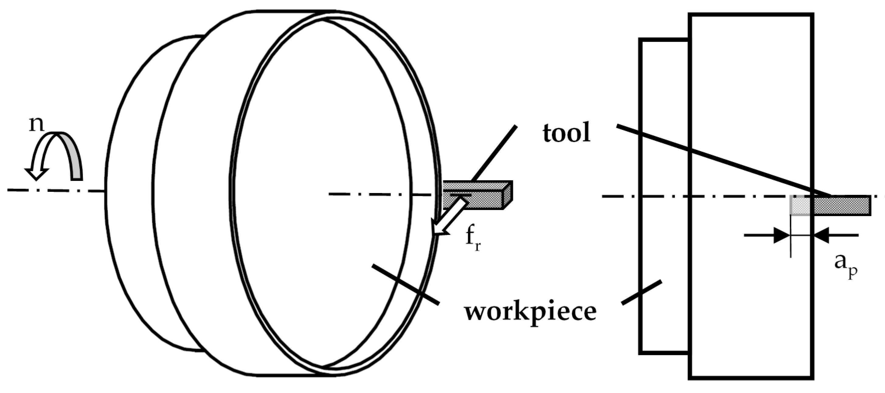
Zielinski and colleagues studied heat-treated 42CrMo4 at 42 HRC, using a 58 mm diameter specimen with a 1 mm-wide ring on its face. The precision-turning experiment used dry cutting at 100 m/min and depths of cut from 7 to 150 µm. The narrow face ring allowed the researchers to isolate machining loads and the resulting near-surface stresses. 2
See the setup before reading the curves
Figure 3 — Specimen, cutting tool and dynamometer.
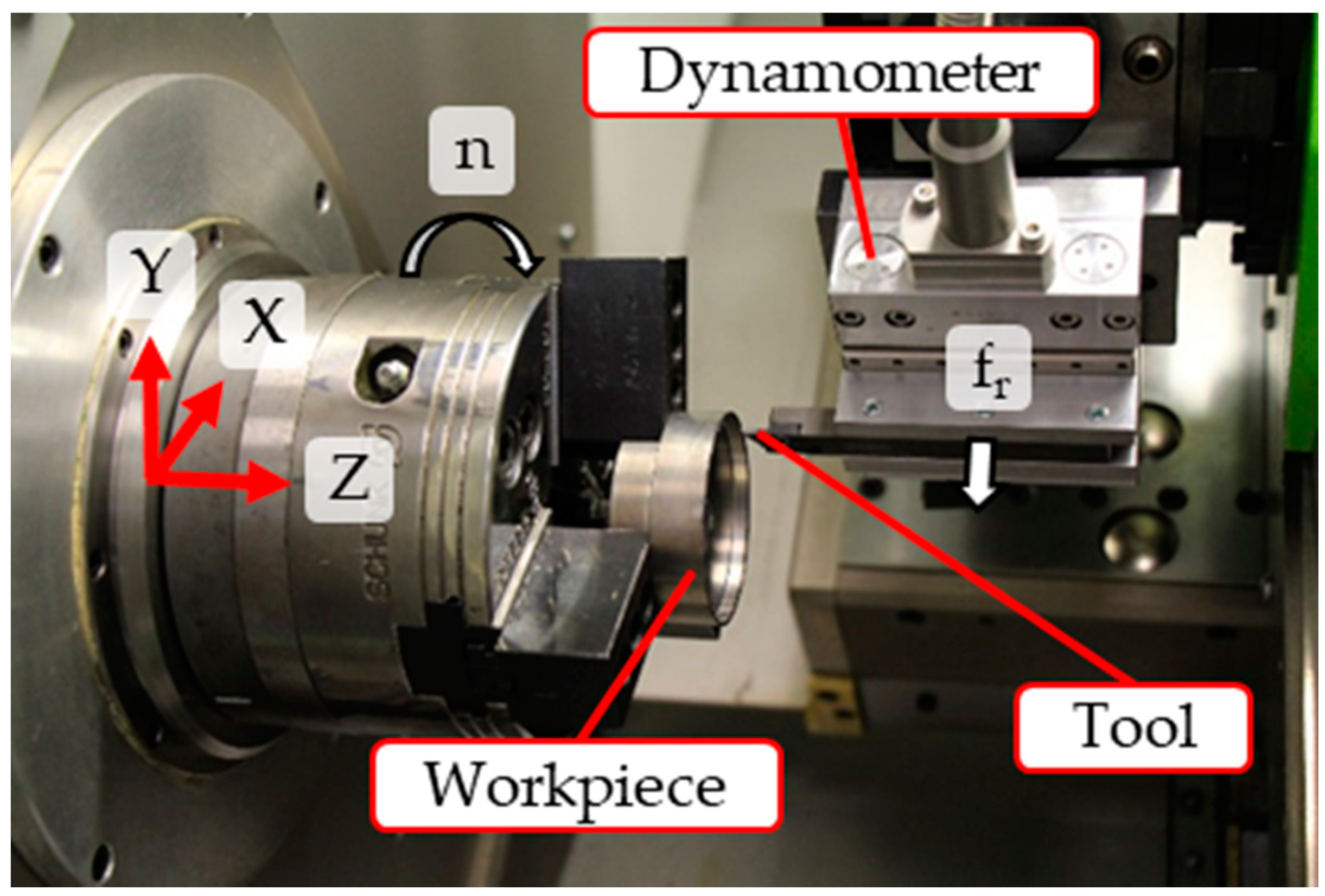
The dynamometer records cutting forces; X-ray diffraction measures the residual stresses afterward.
Select an image to open the full-size original and inspect its labels.
The dynamometer recorded forces during cutting. X-ray diffraction measured residual stresses afterward, with successive electropolishing steps exposing deeper layers for the stress profile.
Figure 4 — Cutting geometry of the narrow face ring.
Swipe across the image to inspect its panels, or select it for the full-size original.
The narrow ring and single tool engagement isolate the cutting event.
Select an image to open the full-size original and inspect its labels.
Cutting load and residual stress are different results
Figure 5 — Cutting and thrust forces rise with depth of cut.
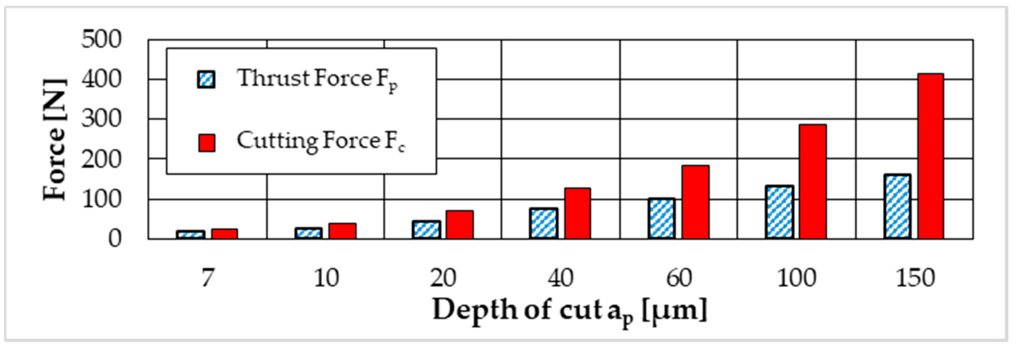
Swipe across the image to inspect its panels, or select it for the full-size original.
Read force in newtons against depth of cut in micrometres.
Select an image to open the full-size original and inspect its labels.
Figure 6 — Residual stresses measured after cutting.
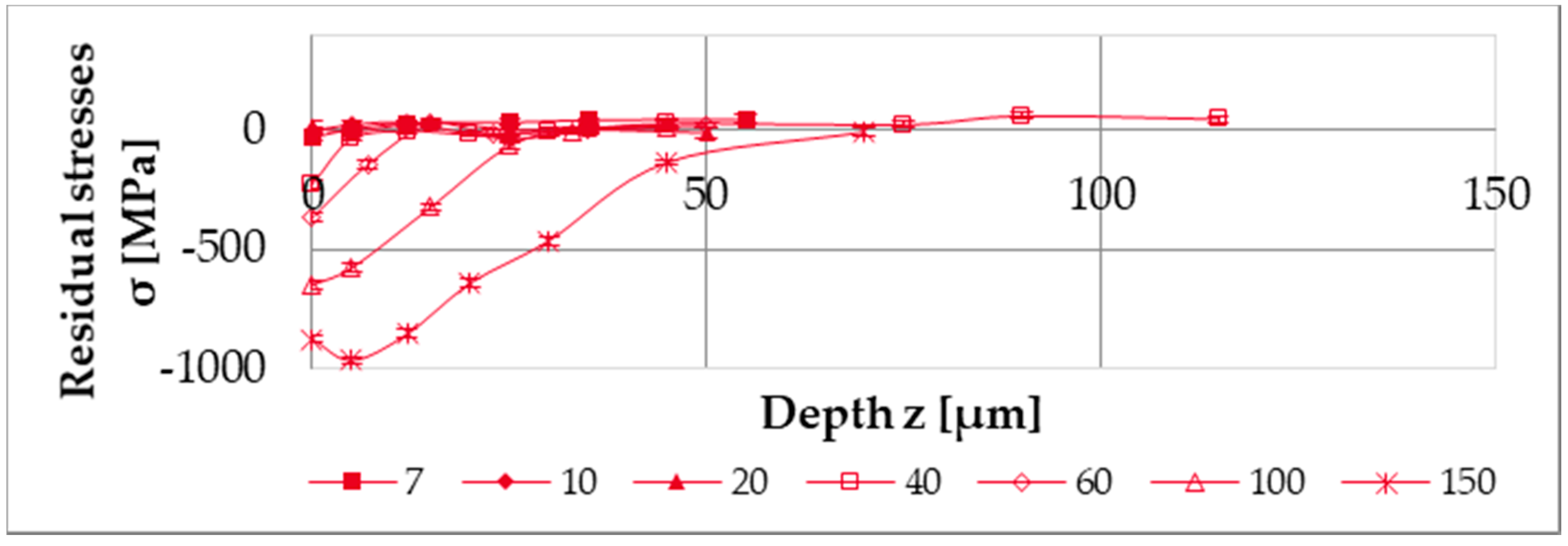
Swipe across the image to inspect its panels, or select it for the full-size original.
Negative values indicate compression. Depth is measured below the finished surface.
Select an image to open the full-size original and inspect its labels.
Figure 6 plots near-surface stress profiles. Under these test conditions, larger cuts produced greater compressive residual stresses and a deeper affected region. The horizontal axis shows how far below the machined surface each reading was taken; negative stress values indicate compression.
Each parameter combination was tested once with a fresh tool and a new specimen. The results show how a controlled change in cutting depth changed both the machining load and the remaining surface stress. 2
A separate 2024 dataset covers 68 machined 42CrMo4+QT specimens with 0.4 mm and 0.8 mm insert-tip radii. It records roughness, residual stress and process-monitoring signals across a range of conditions, including settings deliberately outside the tool’s preferred operating range. This gives manufacturers a useful basis for studying individual process variables. Díaz-Salamanca et al., 2024
For production, qualify the cutting and support strategy using the actual geometry and supplied material condition. Include released-part dimensions in the trial so that cutting performance and dimensional stability are checked together.
5. Build dimensional checks into the process route
Decide first whether final heat treatment takes place before machining or after rough shaping. That decision sets the sequence for allowance, inspection and finishing.
For QT material, measure movement during roughing before adding a thermal operation. Stress relief, when required, is commonly placed between rough machining and finishing. Bodycote advises keeping the stress-relief temperature below the previous temper for hardened-and-tempered parts. Set the cycle from the recorded treatment history and required properties. Bodycote, stress relieving
Figure 7 — Process route for QT stock.
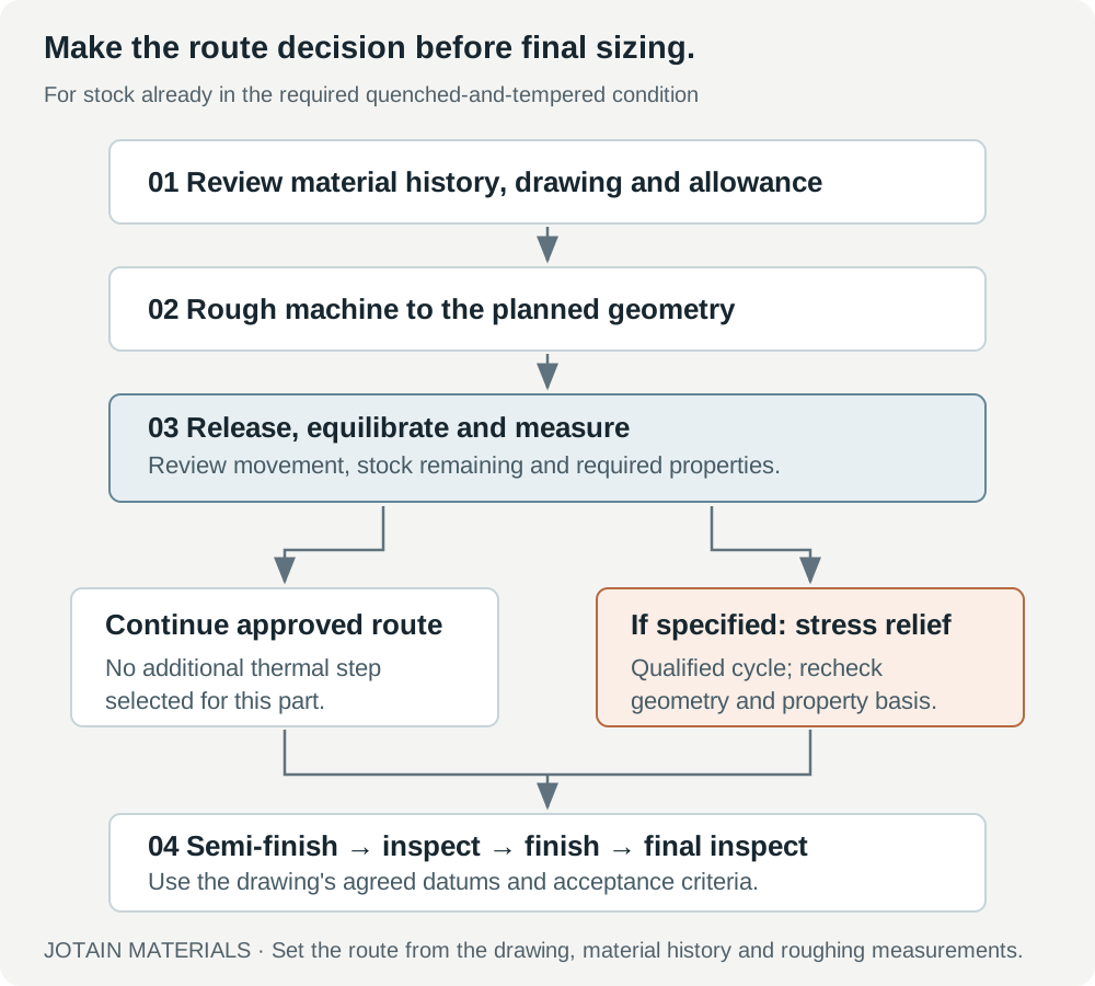
Swipe across the image to inspect its panels, or select it for the full-size original.
Measure the released part after roughing, while correction allowance remains.
Select an image to open the full-size original and inspect its labels.
At the route decision, record the observed movement, remaining allowance, target properties and agreed next operation. If no acceptable process window remains, revise the route rather than silently consuming the finishing stock.
Three distinctions keep this practical:
- Stress relief is not straightening. Reducing residual stress does not promise that an already distorted part returns to its nominal shape.
- Waiting is not a qualified heat-treatment cycle. A pause can make temperature and measurement conditions more comparable; it should not be labelled verified stress relief.
- A final thermal operation needs its own plan. If quenching, induction hardening, nitriding or another treatment remains downstream, discuss its dimensional and property requirements before final sizing.
Record the operation sequence explicitly, including any approved straightening and subsequent inspection. The required evidence belongs to the order; see our heat-treatment certificate guide.
6. Measure the right characteristic at the right stage
A useful inspection record lets another person reproduce the measurement. Specify the feature, datums, support positions, instrument and clamped or released condition. Record the part temperature and account for thermal effects and measurement uncertainty against the 20 °C standard reference temperature. ISO 1:2022; NIST on the reference-temperature principle
Figure 8 — Locate the operation where dimensions change.
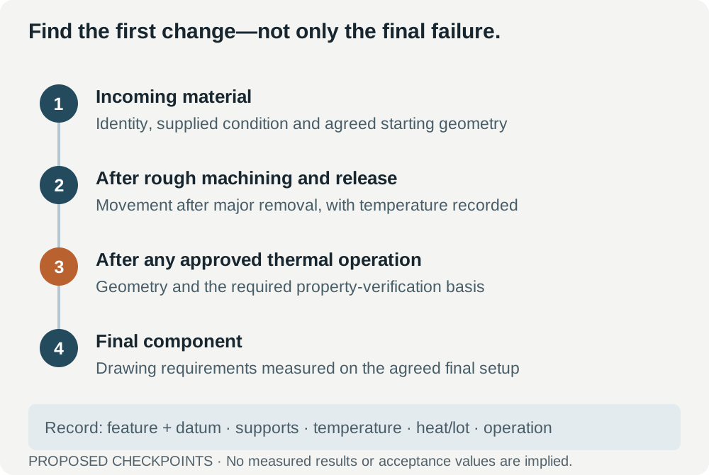
Swipe across the image to inspect its panels, or select it for the full-size original.
Record each result against its process stage, datum, support arrangement and temperature.
Select an image to open the full-size original and inspect its labels.
If residual-stress testing is required, define the question before choosing the method:
| Method | Measurement | Inspection plan |
|---|---|---|
| Dimensional inspection | Specified geometry at a documented process stage | Record datums, supports, temperature and released or clamped condition. |
| Laboratory X-ray diffraction | Residual stress in the sampled crystalline near-surface layer | Specify location and direction; agree a depth-profiling procedure where needed. |
| Hole-drilling strain-gage measurement | Near-surface in-plane residual stress | Select the location, depth range and reporting basis within the method’s applicability. |
NPL’s XRD guide covers sampling depth, specimen geometry and reporting conditions. ASTM E837 covers the hole-drilling approach. For an order requiring residual-stress testing, specify the method, location, direction, process stage and acceptance criteria. NPL GPG52; ASTM E837
For practical drawing and order inputs, see steel-bar straightness requirements.
7. Give the manufacturer the finished-part requirement
JOTAIN Materials operates downstream heat treatment and steel-bar processing. We connect the supplied material condition with the buyer's next manufacturing operation. Our manufacturing role
For a distortion-sensitive component, send the drawing and process context with the enquiry:
- Material and identity: exact grade standard, delivery condition, required mechanical properties and traceability requirements.
- Starting and final geometry: bar diameter and length, smallest finished diameter, bores, flats, keyways, steps and asymmetric features.
- Removal sequence: where the largest stock removal occurs, planned roughing and finishing stages, and any later thermal or surface treatment.
- Workholding and inspection: proposed support arrangement, drawing datums, straightness or run-out requirement, and the stage at which it applies.
- Evidence from an existing problem: incoming and intermediate measurements, heat/lot references, operation sequence and temperature conditions—not only a photograph of the final bent part.
These inputs give technical, production and commercial teams the same problem to work from. Agree who supplies each operation, what condition is handed over, what will be inspected and which records will accompany the material. Additional testing and any special stability requirement must be defined in the order.
Send JOTAIN the drawing, starting size, final geometry and planned machining route. Define the supplied condition around what the part has to become.
Frequently asked questions
Does quenched-and-tempered 4140 still contain residual stress?
It can. Quenching and tempering does not certify an entirely stress-free component, and subsequent manufacturing operations can change the stress state. The published 42CrMo4 study above measured process-dependent residual stresses after machining heat-treated material. 1, 2
Should every 42CrMo4 shaft be stress-relieved after rough machining?
Use the drawing, material history and measured movement after roughing to make that decision. Where thermal stress relief is selected for QT material, keep the cycle compatible with the previous temper and required mechanical properties. 7
Can an HRC result prove that the bar will stay straight?
No. Hardness and geometrical stability are different questions. Do not substitute a hardness value for the specified dimensional checks, process qualification or any separately agreed residual-stress measurement. 2, 4
Does bow appearing after a keyway prove that the steel is defective?
A keyway changes the section and can redistribute residual stress. Compare the incoming material results with measurements immediately before and after cutting, using the same supports and datums. That comparison helps separate material condition, machining effects and inspection differences. 13
RFQ checklist
- Exact grade standard, delivery condition, required properties and traceability.
- Starting size and final geometry, including asymmetric features.
- Roughing, finishing and subsequent thermal or surface-treatment sequence.
- Workholding, datums, dimensional requirements and inspection stage.
- Incoming and intermediate measurements, heat/lot references and temperature conditions.
References
Research Figures 3–6: Zielinski et al. (2021), CC BY 4.0. Diagrams 1, 2, 7 and 8: JOTAIN Materials.
- P. J. Withers and H. K. D. H. Bhadeshia. Residual stress. Part 2 — Nature and origins. Materials Science and Technology 17 (2001), 366–375. Foundational stress mechanisms and measurement-scope distinctions.
- T. Zielinski, A. Vovk, O. Riemer and B. Karpuschewski. An Investigation on Internal Material Loads and Modifications in Precision Turning of Steel 42CrMo4. Micromachines 12 (2021), 526. Original Figures 1, 2, 4 and 5 reproduced unchanged under CC BY 4.0; article Sections 2–3 establish test conditions and results.
- B. L. T. Beekhuis, E. Brinksmeier, M. Garbrecht and J. Sölter. Improving the shape quality of bearing rings in soft turning by using a Fast Tool Servo. Production Engineering 3 (2009), 469.
- ISO. ISO 1101:2017 — Geometrical tolerancing. Catalogue reference.
- R. Radovitzky, MIT OpenCourseWare. Moment of Inertia of Beam Cross Section, Part 02. Unified Engineering, 2021.
- D. Díaz-Salamanca et al. Turning of 42CrMo4+QT under different scenarios: Dataset of machining, roughness and residual stress. Data in Brief 56 (2024), 110793.
- Bodycote. Stress relieving. Process sequencing and tempering conditions.
- ISO. ISO 1:2022 — Standard reference temperature. Official catalogue reference for dimensional and geometrical properties.
- NIST. The 2016 Revision of ISO 1 — Standard Reference Temperature for the Specification of Geometrical and Dimensional Properties. Journal of Research of NIST 121 (2016).
- M. E. Fitzpatrick et al., NPL. Determination of Residual Stresses by X-ray Diffraction, Issue 2, Good Practice Guide 52.
- ASTM International. ASTM E837 — Hole-Drilling Strain-Gage Method. Scope and method reference.
- Ovako. 42CrMo4 material data. Grade variants and section-dependent properties.
- M. Aurrekoetxea, L. N. López de Lacalle and I. Llanos. Machining Stresses and Initial Geometry on Bulk Residual Stresses Characterization by On-Machine Layer Removal. Materials 13 (2020), 1445. Layer-removal experiments on aluminium blanks.
Inquiry support
Unsure which processing route to quote?
Send the drawing or RFQ with the grade, size, condition, processing, inspection, quantity, and destination. We can flag open points before quotation.