

JOTAIN APPLICATIONS
Mining & Industrial Machinery
Grinding rods, machinery blanks and mine support
Heat-treated grinding rods, shaft and pin blanks, threaded bars and ground-support products.
Send dimensions, material condition, operating duty and inspection requirements.
APPLICATIONS
From the Mill to the Mine

Rod-Mill Grinding
Explore Application
Heavy Machinery
Explore Application
Mine & Heading Support
Explore ApplicationGRINDING RODS & MILL DUTY
Rod-Mill Grinding
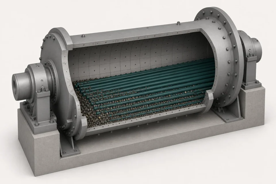
Heat-treated grinding rods for mineral-processing rod mills. Product selection starts with mill geometry, rod dimensions and the actual wear and impact conditions. Compare trial results over matched operating periods.
Project Checklist
- Mill and rod dimensions, feed and operating duty
- Current consumption, breakage and bending history
- Hardness, straightness, ends and lot records
SHAFTS, PINS & THREADED PARTS
Heavy Machinery
Shaft and pin blanks, tie and fastener material and rough-machined heavy parts are reviewed against the OEM drawing. The ruling section, heat-treatment response, fatigue and impact duty govern acceptance.
Project Checklist
- OEM drawing, critical section and machining allowance
- Material, core properties and heat-treatment responsibility
- NDT, dimensions, surface condition and identification
ROCK BOLTS & ADVANCE SUPPORT
Mine & Heading Support
Rock bolts, mechanical anchorage, lattice girders and umbrella pipes are reviewed for the mine or heading support design. Confirm the ground, excavation sequence, installation method and product-specific verification.
Project Checklist
- Ground conditions and temporary or permanent support
- Rod type, anchorage, borehole and connection interfaces
- Installation, inspection and project acceptance
OUR SUPPLY
Grinding Rods & Mining Products
Choose a product to view materials, dimensions and supply condition.
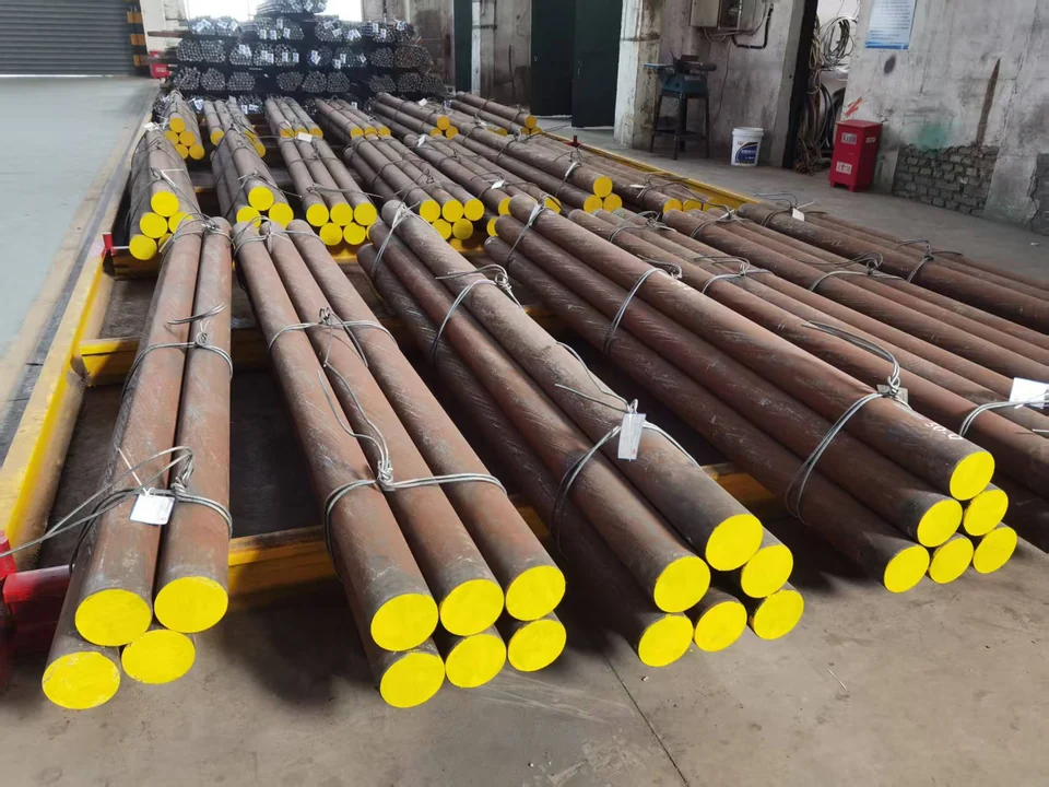
HEAT-TREATED RODS FOR ROD MILLS
Grinding Rods
Heat-treated rods for your mill.
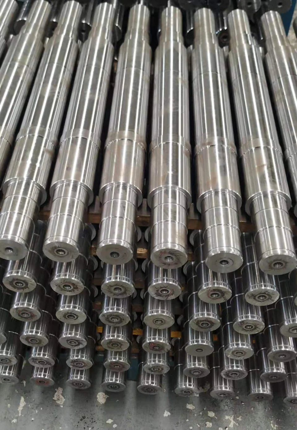
HEAVY ROTATING & ARTICULATED PARTS
Shaft & Pin Blanks
Blanks for heavy-duty machinery.
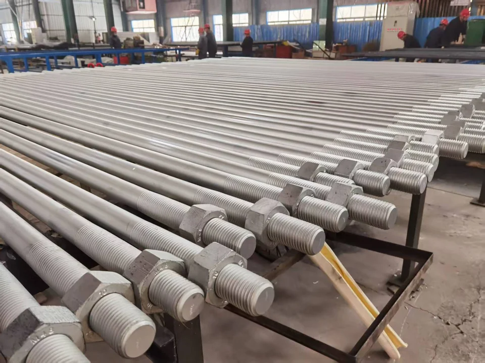
HIGH-LOAD THREADED COMPONENTS
Tie & Fastener Bar
Bar for threaded machine parts.
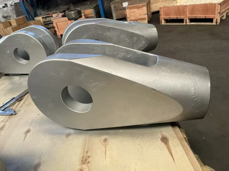
HEAVY COMPONENTS TO DRAWING
Rough-Machined Parts
Prepared for final machining.
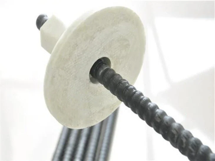
SOLID GFRP ROCK BOLTS
Solid FRP Bolts
Cuttable rods for face support.
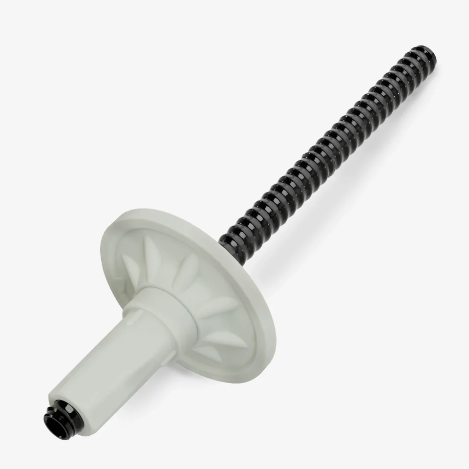
HOLLOW GFRP ROCK BOLTS
Hollow FRP Bolts
Hollow rods for grout injection.
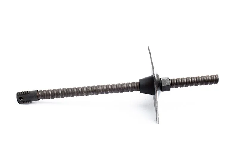
SELF-DRILLING HOLLOW ROCK BOLTS
Self-Drilling Bolts
Drilling and grouting in one route.
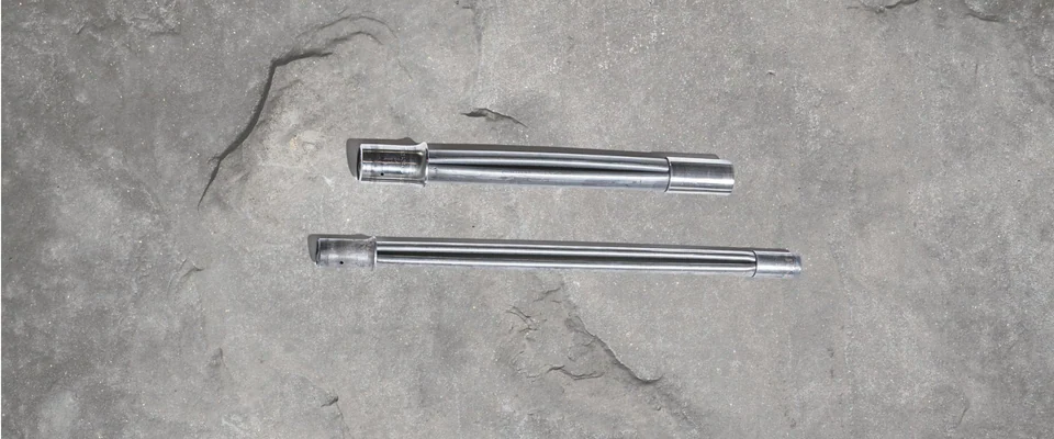
EXPANDABLE FRICTION ROCK BOLTS
Expandable Bolts
Water-expanded steel tube support.
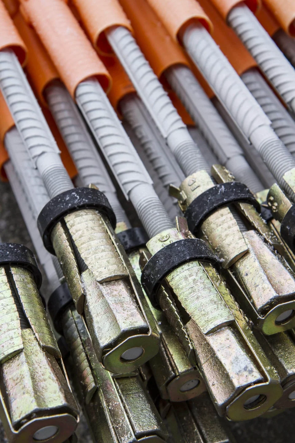
STEEL OR FRP ROCK-BOLT ROUTES
Combination Bolts
Combined anchorage configurations.

EXPANSION-HEAD ROCK ANCHORAGE
Mechanical Rock Bolts
Mechanical anchorage in the rock.
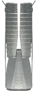
MECHANICAL ANCHOR HEADS
Bail Anchors
Mechanical setting with matched rods.
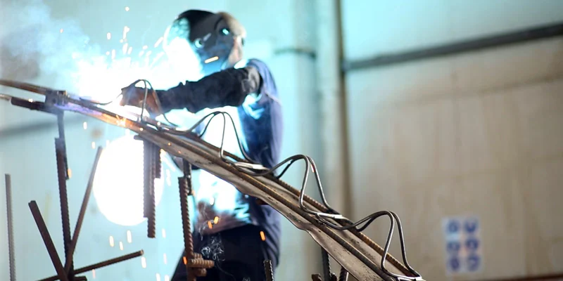
TUNNEL & HEADING SUPPORT
Lattice Girders
Curved steel frames to the specified profile.
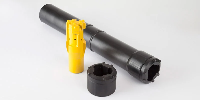
FOREPOLING & ADVANCE SUPPORT
Umbrella Pipes
Pipe canopy ahead of excavation.
Grinding Rods
Specify the rod around the working mill.
JOTAIN supplies finished, heat-treated 65Mn grinding rods with straightening, fixed-length cutting, inspection, marking and export packing. Rod dimensions, heat-treatment response and the balance between wear resistance and toughness are reviewed together against the actual rod-mill duty. Alternative materials require a separate technical review.
- Supply
- Heat-treated, straightened rods cut to the ordered length, with agreed end condition, identification and packing. Confirm diameter, tolerance, usable length and the mill’s handling limits.
- Hardness
- Agree the target band, scale and test method, surface and internal test positions where specified, sampling and heat-treatment lot uniformity. Hardness alone does not establish service life.
- Mill duty
- Provide feed characteristics, mill size and operating conditions, current rod material and size, consumption in kg/t, and any breakage, bending, spalling or tangling history.
- Acceptance
- Confirm straightness measurement and sampling, flat crack-free ends, surface condition, inspection records and trial quantity. Compare trials over matched operating conditions before assessing repeatability.
Shaft & Pin Blanks
Shaft & Pin Blanks
Review the core at the controlling section.
Shaft and pin blanks for heavy rotating and articulated machinery are supplied through the agreed bar or forging route. Diameter, heat-treatment response, cyclic load and impact duty determine the property review; the critical section must be represented by the agreed test location.
- Supply
- QT bar, peeled stock or rough-machined blanks with drawing-defined allowance.
- Section
- Confirm ruling diameter, core toughness, hardness profile, test position and the OEM property targets.
- Inspection
- Agree internal soundness, UT when specified, surface acceptance, straightness, end condition and dimensional reports.
Tie & Fastener Bar
Tie & Fastener Bar
Control the thread-root fatigue zone.
Heat-treated alloy bar and prepared threaded material are reviewed for high-load machinery ties and fasteners. Material properties, preload, engagement and the thread-manufacturing route must suit the purchaser’s peak and cyclic loading requirements.
- Supply
- Heat-treated bar and thread-ready preparation or agreed end machining, with specified mechanical acceptance.
- Interfaces
- Thread standard and class, engagement, preload, thread roots, transition geometry and surface condition.
- Next stage
- Straightness, end condition, machining allowance, surface acceptance and UT where specified.
Rough-Machined Parts
Rough-Machined Parts
Check internal quality before finish machining.
Rough-machined heavy parts are prepared through a rolled or forged material route with agreed machining allowance. The OEM drawing defines the critical section, heat-treatment responsibility, datums and inspection stages before final machining.
- Supply
- Rolled or forged stock, rough machining and a drawing-specific dimensional report.
- Before cutting
- Resolve UT stage and acceptance, internal soundness and the heat-treatment condition at the critical section.
- Allowance
- Confirm datums, stock allowance, straightness and surface condition for the next machining or assembly operation.
Solid FRP Bolts
Solid FRP Bolts
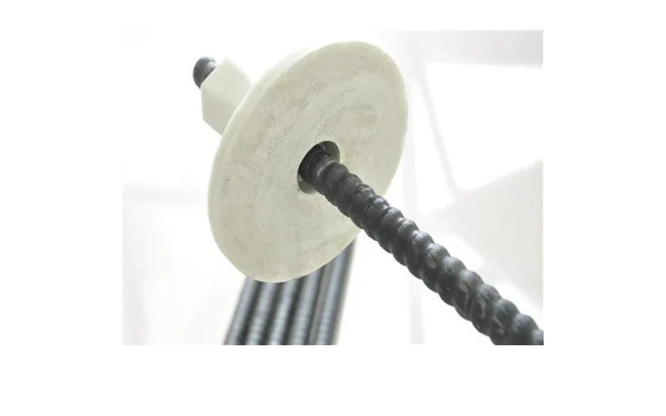
Match a solid tendon to the excavation sequence.
Solid FRP rock bolts provide a cuttable rod route for face reinforcement and ground support where later excavation is planned. The solid GFRP tendon is installed in a pre-drilled hole with the project-specified grout or resin system.
- Rod
- Confirm solid cross-section, profile, diameter, length and required tensile and head-assembly properties.
- Installation
- Agree hole geometry, grout or resin compatibility, cure requirements and installation equipment.
- Mating parts
- Match plate and nut material to the required cuttability, bearing surface and project acceptance.
Hollow FRP Bolts
Hollow FRP Bolts
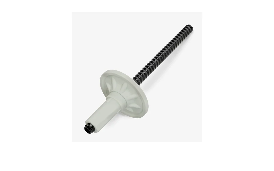
Use the hollow core for the agreed grouting route.
Hollow FRP rock bolts combine a cuttable GFRP tendon with an internal passage for grout. This product route uses a pre-drilled hole; self-drilling bolts are reviewed separately for their drilling and connection requirements.
- Rod
- Confirm outer and inner diameters, length, profile and the required rod and head-assembly acceptance.
- Grouting
- Agree grout compatibility, injection connection, sealing and the specified installation procedure.
- Mating parts
- Confirm plate, nut and any extension interface, including the required cuttability and bearing arrangement.
Self-Drilling Bolts
Self-Drilling Bolts
Coordinate the bar, drill bit and grout path.
A self-drilling hollow rock-bolt route combines a threaded hollow bar, drill bit and grout passage. The ground conditions and installation equipment govern selection, including where a pre-drilled hole cannot remain open for conventional insertion.
- Bar
- Confirm the specified steel or FRP route, outer and inner diameters, thread form and section lengths.
- Interfaces
- Review drill-bit type, coupling engagement, injection connection, bearing plate and nut against the installation method.
- Acceptance
- Specify ground conditions, grout procedure, required support properties, protection and installation or pull-test records.
Expandable Bolts
Expandable Bolts
Match expansion to the borehole and ground.
Expandable friction bolts use a formed steel tube that expands against the borehole wall when installed with high-pressure water. This route is reviewed for roof and wall support with hole dimensions, installation equipment and ground conditions specified together.
- Tube
- Confirm profile, finished length, end fittings, corrosion protection and the required acceptance.
- Installation
- Agree hole size and condition, expansion equipment and the supplier-approved installation procedure.
- Verification
- Specify installation records, inspection and project-required pull testing. Capacity is confirmed for the selected product and ground conditions.
Combination Bolts
Combination Bolts
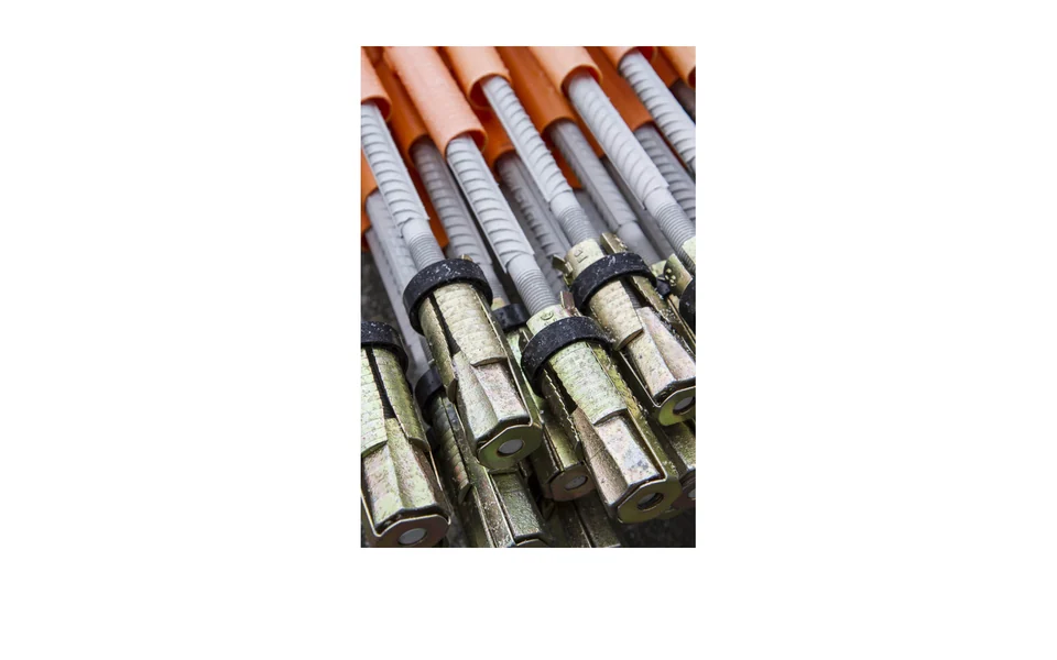
Specify the complete anchorage arrangement.
Combination rock bolts are reviewed as steel or FRP product configurations against the excavation sequence. Specify the intended initial anchorage and subsequent bonding or grouting arrangement, together with cuttability and protection requirements where applicable.
- Configuration
- State the selected steel or FRP route, rod, sleeve or pipe, anchorage head and any grout passage. These are alternative configurations, not an assumed steel–FRP hybrid.
- Sequence
- Confirm immediate-support requirements, later grouting, temporary or permanent duty and the approved installation method.
- Interfaces
- Review plate, nut, connection fit, corrosion protection and project-required system verification.
Mechanical Rock Bolts
Mechanical Rock Bolts
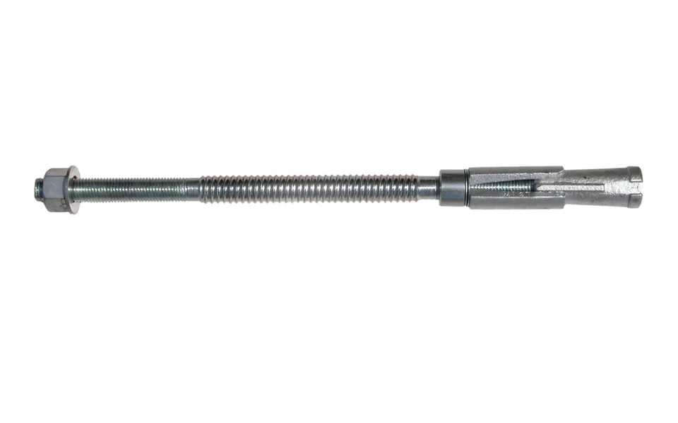
Review the rod and expansion head together.
Mechanical rock-bolt assemblies combine a load-bearing rod with a matched expansion head. The accepted drawing and ground conditions govern the rod, head geometry, hole size and installation requirements.
- Assembly
- Confirm rod material and profile, expansion shell and cone, head connection, bearing plate and nut.
- Installation
- Specify borehole diameter and straightness, rock condition, tensioning method and the approved setting procedure.
- Verification
- Confirm engagement, installed load or testing requirements, corrosion protection and any subsequent grouting. Product ratings and installation acceptance are agreed for the selected assembly.
Bail Anchors
Bail Anchors
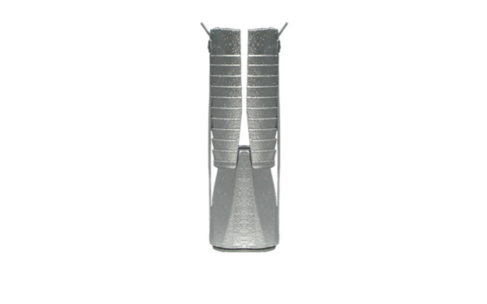
Confirm the head and its mating hardware.
Bail-type mechanical anchors are reviewed with the specified rod and mating hardware. The setting arrangement, hole geometry and ground conditions control selection; the supplied head configuration must match the approved installation procedure.
- Head
- Confirm shell or wedge configuration, rod diameter, thread connection and the required load basis.
- Hardware
- Match the bearing plate, nut and washer arrangement to the head and rod.
- Installation
- Confirm the setting and tensioning method, grout-tube arrangement if specified, and project-required inspection or pull testing.
Lattice Girders
Lattice Girders
Match the frame to the excavation geometry.
Lattice girders are three-dimensional steel frames for tunnel and heading support. Main bars, secondary bars, stiffeners and connection details are reviewed against the purchaser’s support design and excavation profile.
- Geometry
- Confirm radius, frame section, segment lengths, spacing and erection tolerance.
- Connections
- Specify connection plates, footplates, joints and the interface with the surrounding support or lining.
- Supply
- Agree material, fabrication and weld requirements, dimensional checks, marking and delivery sequence.
Umbrella Pipes
Umbrella Pipes
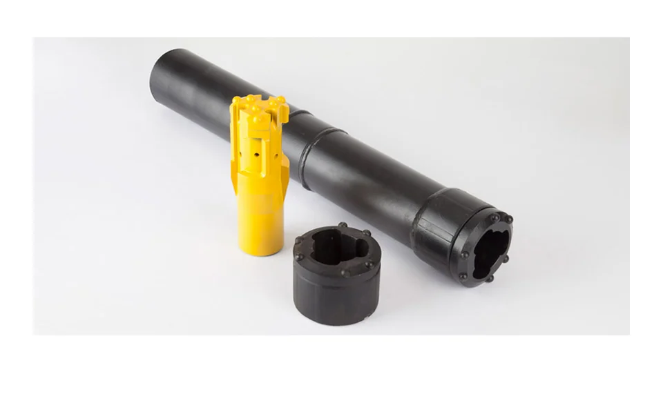
Coordinate the canopy and installation sequence.
Umbrella or forepoling pipes form an advance support canopy ahead of a tunnel or heading. Pipe sections, joints and installation geometry are reviewed for the specified ground conditions and excavation sequence.
- Pipes
- Confirm diameter, wall thickness, section length, steel specification and connection details.
- Layout
- Specify installation angle, pipe spacing, overlap, canopy length and drilling equipment interfaces.
- Acceptance
- Agree joint fit, straightness, grouting details where specified, corrosion protection and inspection records.
Bars & Accessories
Match supply to your project list
Drawing Review
Confirm dimensions, threads and interfaces
Inspection & Records
Agree acceptance and delivery records
Packing & Delivery
Confirm marking, protection and shipment
ACCESSORIES
Accessories for a Coordinated Supply
Connection, anchorage, installation and protection components matched to your project list.
Confirm the complete mechanical anchor head and mating hardware against the selected rod, hole geometry and installation procedure.
Anchor Heads & Accessories
MATCHED EXPANSION ASSEMBLY
Head assembly and specified accessories corresponding to the mechanical rock-bolt route. Confirm the actual model, shell, cone, rod connection, plate, nut and washer configuration.
GRINDING ROD ORDER CHECKLIST
Start with Your Rod-Mill Requirements
Define the delivered rod, the heat-treatment result and the trial conditions before quotation.
Rod Size & Mill Fit
Confirm finished diameter, tolerance, ordered length, mill dimensions, charging and handling constraints, straightness and end condition.
Add to Project EnquiryHardness & Lot Control
Agree material, hardness band, test method and positions, sampling, heat-treatment records and the balance between wear and impact resistance.
Add to Project EnquiryControlled Mill Trial
Record feed and operating duty, current consumption in kg/t, breakage and bending. Compare matching operating periods and agree the inspection and trial quantity.
Add to Project Enquiry- Mill Duty & Rod Size
- Material & Heat Treatment
- Inspection Agreement
- Trial Batch & Records
- Packing & Delivery
SUPPLY SCOPE
Grinding Rod Supply.
Clear Engineering Interfaces.
JOTAIN supplies heat-treated grinding rods, machinery material and prepared components, with ground-support products reviewed against the purchaser’s mine and project specifications.
- Our scope
- Confirm product form, material and condition, dimensions, end preparation, ordered testing, traceability, packing and delivery. Grinding-rod supply includes heat treatment, straightening and fixed-length cutting.
- Purchaser
- Define mill and machinery design, operating duty, OEM requirements, ground-support design, installation and the acceptance basis for each product.
WORKING CONDITIONS & ACCEPTANCE
Balance Hardness, Toughness & Section Size
The actual failure mode and working conditions guide the product and material review.
Failure Mode
Abrasion, impact, fatigue or combined duty
Section
Hardenability and core properties
Geometry
Straightness, ends, allowance and fit
Verification
Hardness profile, properties and integrity
Product specifications
Review the Conditions Behind the Specification
Grinding rods, machine parts and ground-support products have different acceptance requirements.
Wear & Impact
Review damage alongside the hardness result
For grinding rods, abrasive wear, impact severity, breakage and spalling history must be considered together. A hardness reading at one location does not fully characterise the rod or predict mill performance.
- Mill inputs
- Feed, mill duty, current rod material and dimensions, consumption, breakage, bending and replacement practice.
- Acceptance
- Target hardness and profile, heat-treatment consistency, toughness, straightness and end condition.
Section & Fatigue
Represent the critical section and thread root
For shafts, pins and heavy parts, diameter and geometry affect heat-treatment response and core properties. Threaded machine parts additionally require preload, engagement and thread-root review.
- Properties
- Section hardenability, core toughness, hardness profile, cyclic and impact demand.
- Interfaces
- Thread manufacture, transition geometry, surface condition, machining allowance and assembly fit.
Manufacturing & Ground Support
Confirm the next operation and installation route
Specify the inspection stage before further machining or installation. For rock bolts and heading support, the purchaser’s ground model and installation design define the selected product and required verification.
- Machinery
- UT stage and acceptance, surface condition, datum strategy, machining allowance and dimensions.
- Support
- Hole or excavation geometry, anchorage, grout or expansion method, protection and project-required installation tests.
GRINDING RODS & MACHINERY MATERIALS
Confirm the Product Before the Grade
Finished grinding-rod requirements and machinery bar ranges are reviewed separately against the requirements of each order.
Heat-Treated Grinding Rods
Material properties and dimensions
- Standard
- 65Mn primary route; 40Cr or a defined Cr-Mo route requires separate review
- Supply / Processing
- Heat treatment, straightening, cutting, marking and packing
- Delivery Condition
- Heat treated; flat crack-free ends
- Use in Review
- Rod-mill duty with agreed hardness profile, impact balance and dimensional acceptance.
- Application Limits
- Agree HRC band, method and positions, diameter and tolerance, straightness measurement, lot sampling and any operating trial.
34CrNiMo6
Material properties and dimensions
- Standard
- 34CrNiMo6; verify any proposed SAE 4340 substitution
- Supply / Processing
- Hot rolled / forged / machined
- Delivery Condition
- QT or forged route
- Use in Review
- Candidate for heavy sections requiring higher hardenability and core toughness.
- Application Limits
- Use only when the OEM specification and property targets require it; section size and test location govern.
42CrMo4 / 4140
Material properties and dimensions
- Standard
- 42CrMo4 (ISO 683-2) / SAE 4140 (SAE J404)
- Supply / Processing
- Black / peeled / machined
- Delivery Condition
- QT or rough-machined
- Use in Review
- Candidate high-strength route for shafts, pins and heavy components.
- Application Limits
- Confirm product standard, property targets, test position, sampling and result documents. Cross-standard substitution requires verification.
STEEL PROCESSING & DELIVERY
From the Agreed Route to the Delivered Rod
A steel-bar and machinery-component sequence; the exact operations follow the selected product and order.
- 01
Approved Bar or Forging
- 02
Heat Treatment
- 03
Straightening & Cutting
- 04
Peeling or Rough Machining
- 05
Hardness & Integrity Checks
- 06
End Protection & Packing
INSPECTION & RECORDS
Confirm Inspection
Before Production.
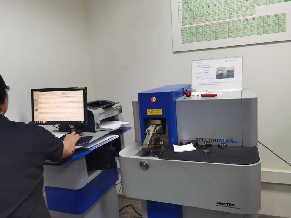
Agree test positions, acceptance criteria, inspection timing, marking and release records before production. Identify the relevant checks for grinding rods, load-bearing blanks and ground-support products.
Inspection items
Grinding-Rod Control
Hardness target and profile, heat-treatment and lot records, straightness, length, surface and end condition.
Load-Bearing Properties
Tensile properties, impact tests when specified and acceptance criteria appropriate to the section size of machinery parts.
Integrity & Geometry
UT when specified, surface acceptance, machining allowance and dimensions; product-specific support inspection and installation records.
REFERENCE & ORDER BASIS
Standards for Your Order
Use the approved drawings, project specification, inspection plan and stated editions of the standards.
ISO 683-2
Technical delivery context for alloy steels used in quenched-and-tempered machine parts.
Open ReferenceISO 6336-1
Gear load-capacity design context where the OEM supplies gear-related duty inputs; not a grinding-rod or rock-bolt material approval.
Open ReferenceSUPPLY SUPPORT
From Specification to Delivery
Processing Capabilities
Explore heat treatment, cut lengths, surface finishing and thread preparation. Confirm the supply stage against your drawings.
Explore ProcessingInspection & Traceability
Confirm heat identification, dimensions, mechanical properties and specified inspections, together with the order documents.
View Quality & DocumentsTechnical Resources
Bring material standards, dimensions and technical specifications to support the review of bars and accessories for your enquiry.
Browse ResourcesDiscuss your project
Send your requirements directly to JOTAIN. We will reply to your email.