
MICROSTRUCTURE / SURFACE CONDITION / QUALITY CONTROL
Decarburization in Steel Bars: Why the Surface Can Be Too Soft
Follow the carbon from the furnace to the finished surface. Read the micrographs, measure the affected layer, and put a precise requirement on the order.
A steel bar can have the correct chemistry on its certificate, respond well to quenching in its interior, and still carry a soft layer at the surface. The explanation is often decarburization: a loss of carbon from the steel next to the surface during heating. That layer then responds differently to the same heat treatment.
Open image at full size ↗
The distinction matters wherever the surface does useful work: a grinding rod meeting ore, a shaft carrying cyclic bending, or a thread transferring load. It also matters before machining. The material allowance has to remove the affected metal while leaving enough stock to achieve the finished geometry.
For a buyer or inspector, the investigation follows three questions. What structure is present at the edge? How far does the change extend? Which of those layers will remain in the finished product? A polished cross-section, a properly positioned hardness traverse and a clear description of the manufacturing stage answer those questions together.
1. What happens to the carbon during heating?
Carbon has a strong influence on the structures that form when steel cools. In a quenched carbon or low-alloy steel, the amount of carbon available in austenite helps determine the hardness of the martensite that forms. A surface region that has lost carbon starts that transformation with a different composition from the interior. The National Bureau of Standards' classic treatment of steel heat treatment illustrates the resulting contrast directly. [1]
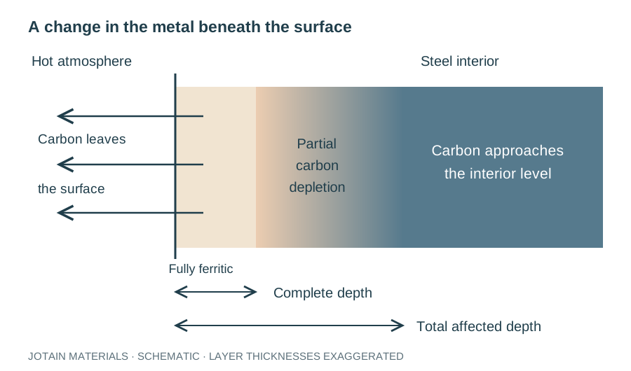
At elevated temperature, the furnace atmosphere and the steel surface interact. When the atmosphere favours carbon removal, reactions at the boundary draw carbon out of the steel. Carbon from deeper material diffuses towards that boundary. Over time, a concentration gradient develops: lower carbon near the outside, progressively recovering towards the interior.
Both the surface reaction and diffusion matter. So do temperature, time, atmosphere, alloy composition and the scale already present. In an oxidizing atmosphere, iron is also being consumed to form scale. The metallic boundary can therefore move while the carbon profile develops. Zorc and colleagues examined this interaction in C45 steel and showed why the remaining visible layer has to be interpreted together with oxidation. [2]
This is why a dark surface and a decarburized surface are different observations. The first concerns the appearance of the outside; the second concerns the composition of the metal beneath it.
Open image at full size ↗
Why reheating and quenching may leave the problem in place
Quenching changes the structure produced from the austenite. It does not supply the carbon that has already left the surface. A repeat heat treatment therefore needs a considered purpose: correcting the transformation route, removing the affected material, or deliberately restoring carbon through a separately specified treatment. Simply increasing quench severity addresses cooling rate, while carbon loss requires its own remedy. [1]
2. Read the microstructure from the edge inward
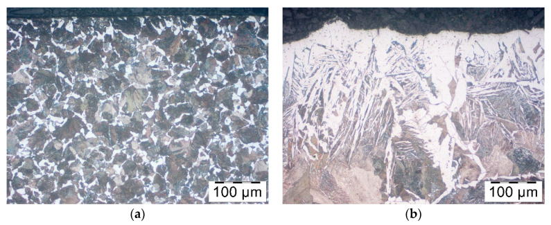
Start by locating the actual metal boundary. On a mounted specimen, the dark region outside the steel may be mounting resin, an oxide layer, or both. Follow the boundary along the section before studying the structure beneath it.
In complete decarburization, carbon depletion is sufficient to leave a ferritic surface layer. On an appropriately etched section of many carbon and low-alloy steels, this appears as a comparatively light band. Its thickness may vary along the edge. The ferrite grains can also extend into the underlying structure rather than forming a perfectly straight boundary.
In partial decarburization, the carbon content has fallen without producing an entirely ferritic layer. In a ferrite–pearlite structure, the change may appear as an increased ferrite fraction near the edge. In quenched and tempered material, changes in etching response and hardness can be more informative than the presence of an obvious white band. Buehler's fastener-metallography guidance describes this distinction and the importance of preserving the outer edge during preparation. [3]
Open image at full size ↗
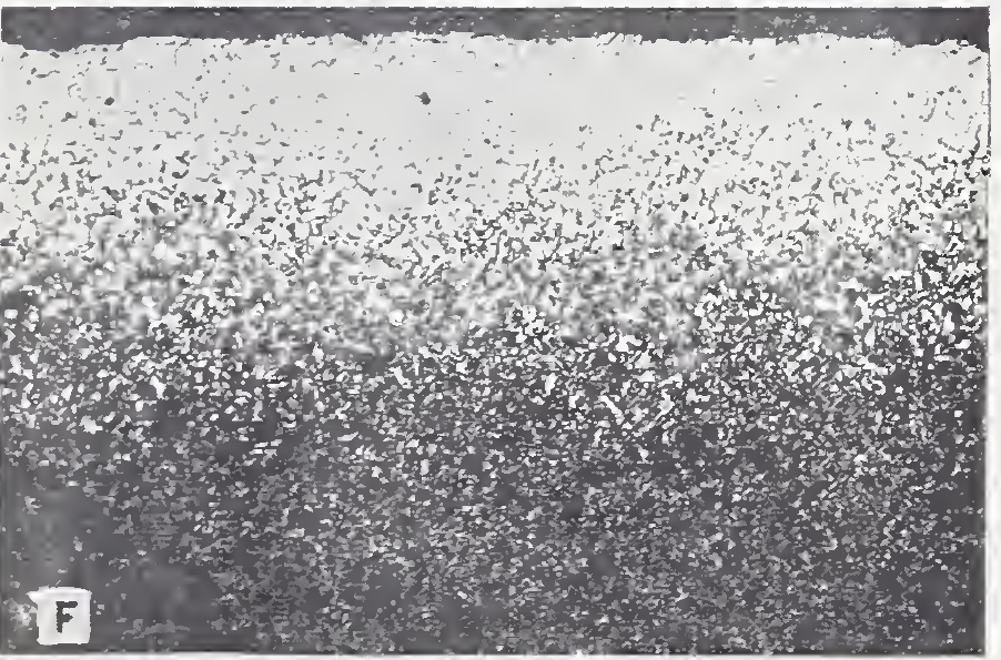
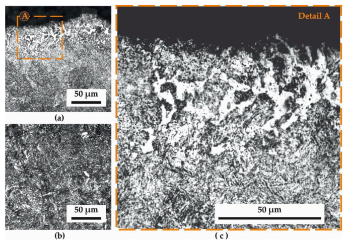
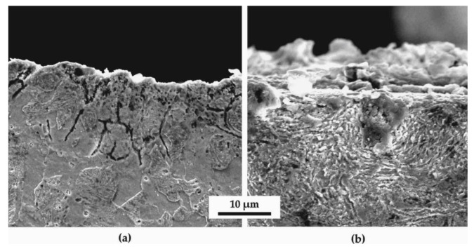
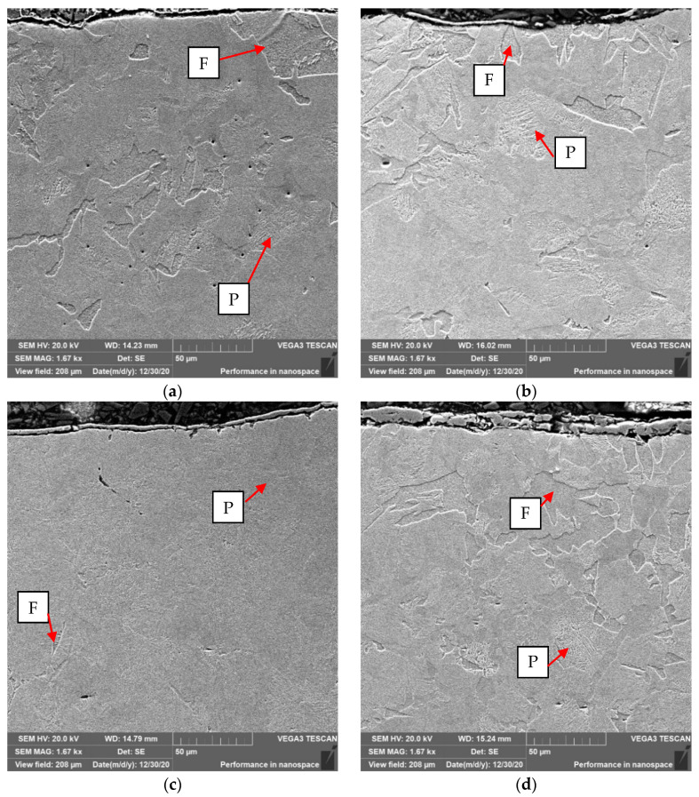
The historical micrograph above is deliberately simple: the outer zone remained soft while the interior hardened. The next figures compare the surface and interior of 51CrV4 leaf-spring steel. Pappa and colleagues present optical and SEM views before and after stress shot peening. [4]
Open image at full size ↗
Open image at full size ↗
A useful micrograph includes enough interior material to establish a reference. A tightly framed photograph of the edge alone leaves the reader guessing what the original structure looked like. Ask for the specimen identity, section orientation, preparation condition, etchant, scale bar and marked measurement positions with the image.
3. Scale removal and decarburization removal are different operations
Shot blasting or pickling can remove oxide scale and reveal a clean-looking metallic surface. Carbon depletion extends into the steel itself. Whether it remains after cleaning depends on how much metal was removed and how deep the affected layer extended.
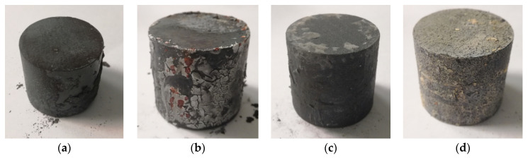
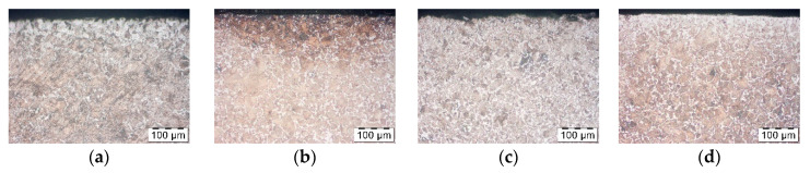
The comparison below makes this distinction tangible. Widomski and colleagues photographed C45 specimens after heating and examined their cross-sections. The outside surfaces tell us about scale and coating behaviour; the polished sections reveal the underlying microstructure. These are complementary views of the same processing question. [5]
Open image at full size ↗
Open image at full size ↗
For inspection, preserve the sequence in the record: as heated, descaled, peeled or turned, and finally heat treated if another thermal operation follows. A depth measured before machining answers a different question from a depth measured on the delivered surface.
The same distinction applies to the reference plane. Scale thickness is outside the current metallic boundary. Decarburization depth is measured into the metal from the defined surface. If material has already been removed, record that operation so the next reader knows which surface is represented.
4. “Decarburization depth” needs an endpoint
A statement such as “decarburization: 0.20 mm” is incomplete until the endpoint is identified. Three descriptions commonly arise in an inspection discussion:
| Description | What is being located? | What should accompany the result? |
|---|---|---|
| Complete decarburization depth | The inner boundary of the fully ferritic surface layer. | Microstructure, measurement positions and the rule for reporting local variation. |
| Total decarburization depth | The extent of complete plus partial carbon depletion, judged by the specified method. | Method, reference interior and the criterion used to identify recovery. |
| Depth to a specified hardness | The position at which the agreed hardness criterion is reached. | Hardness scale, force, dwell, traverse geometry and the chosen hardness criterion. |
The third is a useful functional measurement, but it needs to be named precisely. Hardness is affected by structure and treatment as well as carbon. A hardness-defined boundary and a metallographic boundary can consequently lie at different positions.
ISO 3887:2023 addresses the determination of decarburization depth in steel products. ASTM E1077-14(2021) describes screening, microscopic, microindentation and chemical approaches. The ASTM public scope specifically distinguishes their applications; microindentation is particularly suited to hardened specimens with relatively uniform structures. State the method and edition in the order, then state the acceptance requirement separately. [6] [7]
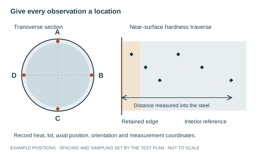
Around a bar circumference, report the individual observations needed to explain the result. If the acceptance rule controls a maximum, a low average cannot stand in for the deepest observed region. A marked section photograph gives that number a physical location.
5. Use hardness to map the layer
A hardness traverse puts a series of indents at known distances from a prepared edge. It can reveal a soft surface region, the transition below it and the comparatively stable interior. For a decarburization investigation, the positions close to the edge deserve particular attention.
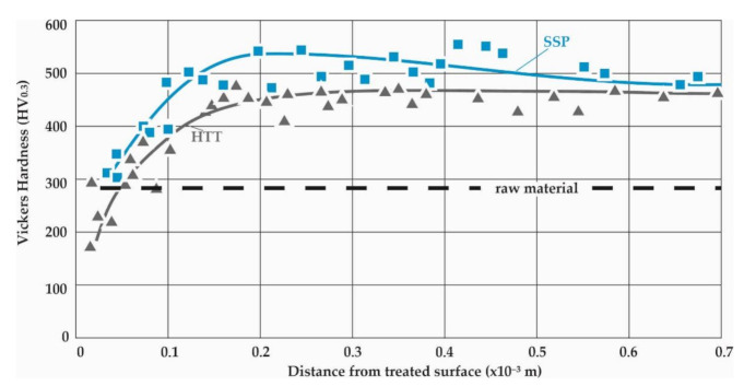
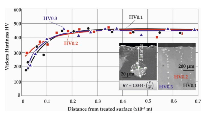
Pappa and colleagues also measured the profiles below. The surface remains softer than the interior after heat treatment and after subsequent stress shot peening. [4] Interpret a hardness profile against the whole manufacturing sequence.
Open image at full size ↗
Match the size of the measurement to the size of the layer
A large indent samples a larger volume. An indent placed too close to the edge, or too near another indent, can also give a distorted result. The laboratory should select the force, spacing and edge distance as a coherent test arrangement, following the applicable method.
ASTM E384 addresses microindentation hardness and its use in examining changes over short distances. Retain the actual test designation and force in the report. “HV” alone loses part of the information; “HV0.3” identifies a Vickers result obtained with a 0.3 kgf test force. Keep the dwell time and individual readings with the profile. [8]
Open image at full size ↗
A handheld or bench surface-hardness reading is useful for its intended acceptance check. Its ability to resolve a thin layer depends on the test method, indentation size, surface preparation and specimen geometry. For a shallow gradient, a prepared cross-section gives the measurement a known depth coordinate. Rockwell testing has its own specimen and procedural requirements, addressed by ASTM E18. [9]
For grinding rods, separate two scales of investigation. A near-surface traverse resolves carbon depletion at the edge. A broader radial profile examines the hardening response through the working section. Place both on the sampling plan when both are relevant. The grinding-rod hardness-profile guide explains the second task in more detail.
Open image at full size ↗
6. A reliable result begins at the cutting machine
The layer being measured may be small enough to damage or remove during preparation. Good microscopy begins by preserving it.
Choose the sampling location while the bar still has its heat and treatment-lot identity. Record the distance from the end, circumferential position and surface condition. A transverse section is useful for examining a round bar's circumference. A longitudinal section may be needed to follow a local feature or to inspect a thread in the plane required by its product specification.
Use a controlled sectioning method with suitable cooling. Then mount the specimen so the edge remains supported through grinding and polishing. Struers identifies cutting heat and edge retention as central concerns in preparing hardened steels; ASTM E3 provides the general framework for specimen preparation. [10] [11]
| Preparation step | What the metallographer is trying to preserve | What a poor preparation can introduce |
|---|---|---|
| Sectioning | The structure present in the supplied material. | Local heating, deformation or a damaged cut face. |
| Mounting | A supported, clearly identifiable outer edge. | Gaps at the resin–metal interface and loss of edge support. |
| Grinding and polishing | A flat section through the retained surface layer. | Edge rounding, relief, scratches or removal of the region of interest. |
| Etching | Contrast appropriate to the steel and its condition. | Obscured features or misleading contrast from an unsuitable procedure. |
| Hardness measurement | Well-resolved indents at recorded coordinates. | Edge interaction, overlapping influence zones or poorly measured impressions. |
Examine the polished surface before etching to locate the boundary and obvious preparation defects. For microscopy, select an etching procedure suited to the material and record it; ASTM E407 covers metallographic etching methods. [12] For hardness, retain a surface on which the indent diagonals can be measured clearly. Where both examinations are needed, plan their sequence with the laboratory.
If a result is unexpected, revisit the specimen and the raw images before changing the furnace programme. Repreparing an edge or measuring a second identified position may explain the discrepancy more directly than a new heat-treatment trial.
7. Time and temperature have to be read together
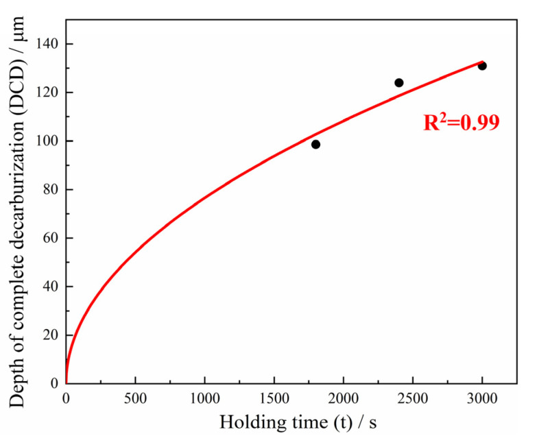
Longer exposure provides more time for carbon transport. Temperature changes diffusion, phase balance and the reactions at the surface. Oxidation changes the boundary as well. The resulting depth therefore depends on a process history, rather than one temperature written on a certificate. [2]
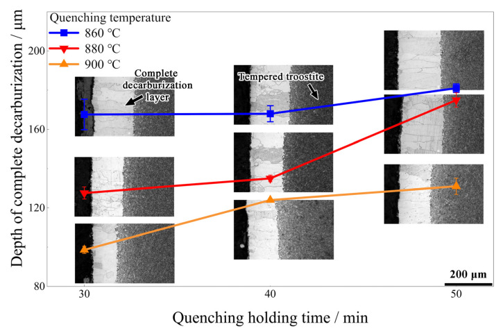
Wang and colleagues' work on 38Si7 spring steel offers a useful example. Their measurements distinguish complete decarburization and compare specified temperature–time combinations. Over the tested range, the fully decarburized layer was smaller at the higher temperature, while a longer hold increased its depth. Read that result with its definition of depth: complete ferritic-layer thickness is only one part of the surface condition. [13]
Open image at full size ↗
Open image at full size ↗
The manufacturing response is to identify which part of the cycle produces the unwanted surface change. Consider the incoming bar, heating before rolling or forging, intermediate annealing, austenitizing, furnace delays and subsequent treatments. A short nominal soak can coexist with substantial total hot exposure if transfers or interruptions extend the cycle.
Atmosphere control belongs in that investigation. Furnace gas composition, moisture, leakage and load conditions determine what the hot surface encounters. Review those records together with the actual heating history and the section being processed. When a protective coating is used, assess it through the complete operation, including its application and its behaviour during heating and deformation.
Open image at full size ↗
The useful process comparison keeps the material and observation method consistent. Compare identified positions, equivalent stages and the same depth criterion. Otherwise, a change in sampling or surface removal can look like an improvement in furnace performance.
8. What this means for grinding rods, shafts and threads
Grinding rods: separate the first layer from the working section
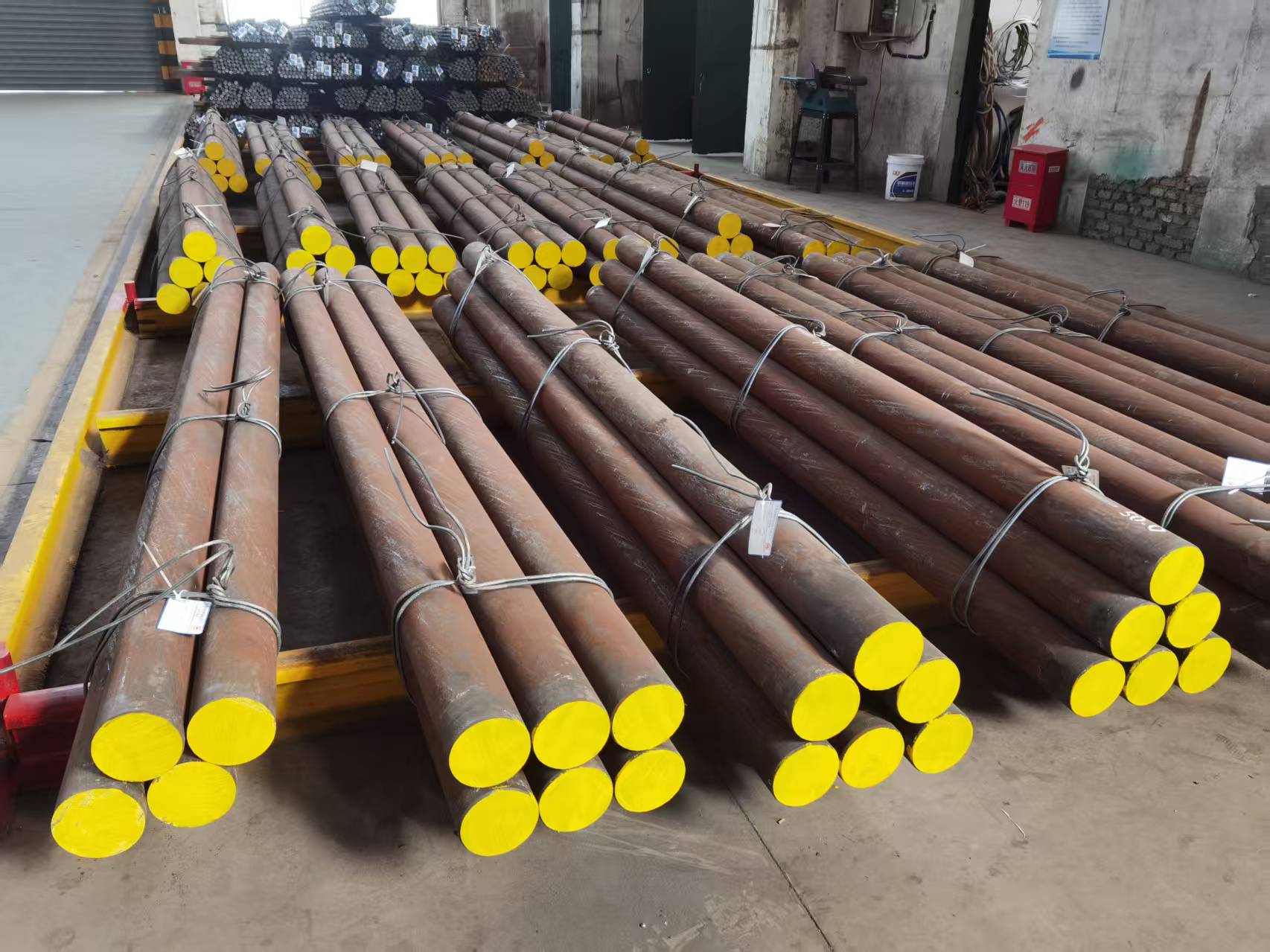
For a grinding rod, the outside is the first material exposed to contact and wear. An unwanted soft layer changes that starting condition. The engineering question is how deep it extends, how it relates to the intended hardness profile, and what the rod's measured behaviour looks like in the mill.
Keep the decarburization assessment beside the radial hardness profile, microstructure, geometry and treatment record. Then examine wear, bending and breakage separately in the operating record. A grade designation or a single surface reading leaves much of that story unresolved. The broader heat-treatment guide explains how carbon, structure and hardenability fit together.
Open image at full size ↗
Shafts and machined bars: follow the surface that survives
On a bar supplied for machining, the as-delivered outside may later become swarf. The finished shaft's surface is what carries the final contact or bending duty. Establish which material will be removed and whether another high-temperature operation follows. The inspection plan should match that sequence.
A thin affected layer can still deserve attention on a highly stressed finished surface, even though it represents a small fraction of the bar's cross-sectional area. Evaluate its position and the component's loading; percentage of bulk material is a poor guide to the significance of a surface defect.
Threads: use the finished geometry
A thread places crests, flanks and roots in different locations relative to the original bar surface. Cutting and rolling also create different material paths. The section and measurements must represent the finished thread and its governing product requirement. Buehler's guidance illustrates why a longitudinal section close to the thread axis is used for that assessment. [3]
These applications share the same metallurgical mechanism, but their acceptance decisions follow different surfaces, manufacturing stages and duties.
9. Work out the machining allowance on radius
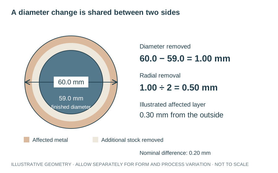
Peeling, turning or grinding can remove a decarburized layer if enough metal is removed around the entire surface. Specify the allowance against the deepest relevant observation, dimensional variation, form and the planned finishing sequence. Nominal diameter reduction alone can hide insufficient local cleanup on an eccentric or bowed bar.
For a concentric round bar, the geometric relationship is straightforward:
Worked geometry example. Turning a 60.0 mm bar to 59.0 mm removes 0.50 mm per side. Suppose an inspection has measured a maximum total decarburization depth of 0.30 mm. The nominal geometric difference is then 0.20 mm. These are illustrative dimensions: the drawing and inspection plan still have to account for bar form, size variation, positioning and the agreed cleanup margin.
Open image at full size ↗
The timing of removal is just as significant. If the bar is peeled and subsequently heated in an atmosphere that removes carbon, the newly exposed surface can develop a new affected layer. Identify the last thermal operation before deciding where the final acceptance test belongs.
The machining-allowance guide discusses the wider relationship between incoming stock and the finished component. For decarburization, make the controlled surface and the remaining stock explicit.
10. Put a complete requirement on the order
The test method tells the laboratory how to examine the material. The product specification, drawing and purchase agreement tell it what result is acceptable. There is no single depth that suits every bar, thread or grinding rod.
Build the requirement in the same order that the material will be identified, sampled and examined:
| Item to agree | What belongs in the purchase or inspection document |
|---|---|
| Material and condition | Grade, governing product standard, size and delivery condition. |
| Controlled surface | As rolled, descaled, peeled, ground, heat treated or finished component; identify later operations. |
| Meaning of depth | Complete, total, or depth to a specified hardness; define the endpoint. |
| Test method | Standard and edition; microscopy and/or the specified hardness method. |
| Sampling | Heat and treatment-lot basis, number of samples, axial and circumferential positions, section orientation. |
| Acceptance | Applicable limit, units, maximum or other agreed statistic, and treatment of local variation. |
| Hardness details | Scale, force, dwell, positions, spacing and the interior or specified reference criterion. |
| Report | Marked specimen map, individual results, scale-bearing images, hardness table and traceability. |
| Disposition | Retest arrangements, segregation, rework approval and the stage of reinspection. |
A practical wording pattern
Assess decarburization on the specified delivery surface using the agreed edition of ISO 3887 or ASTM E1077. Report the requested complete and/or total depth at the sampling locations in the inspection plan. Apply the depth limit and reporting rule stated on the drawing or purchase order. Where a hardness traverse is specified, include the test designation, force, dwell, distance of every reading from the surface and the endpoint criterion. Identify each specimen by steel heat, treatment lot and position, and attach the marked cross-section images.
Select the required method and complete the fields before ordering. Where further machining is planned, attach the incoming and finished dimensions and identify the operation after which the decarburization requirement applies.
Download the decarburization inspection checklist
For a JOTAIN enquiry, send the grade, bar size, supply condition, finished drawing where applicable, and the required decarburization assessment. Those details allow the surface condition, machining route and inspection documents to be discussed against the same requirement. Discuss a requirement with JOTAIN.
Questions that come up during inspection
Does a correct carbon result on the material certificate rule out surface decarburization?
The certificate's chemistry result represents the sample and analysis reported there. A carbon gradient confined to the bar surface requires an examination of that region. Keep the heat chemistry as the material reference and assess the delivered surface with the specified decarburization method.
Is a low surface-hardness reading enough to identify decarburization?
Treat it as a reason to investigate. Surface preparation, test geometry, local structure and the heat-treatment response can also affect the reading. A cross-section that connects microstructure with hardness at known depths provides a much stronger basis for identifying the cause.
Can partial decarburization exist without a continuous white ferrite band?
Yes. Carbon depletion can change the structure and hardness before a fully ferritic layer develops. Examine the transition to the interior, use an appropriate etch, and apply the method required by the order. A complete-decarburization measurement and a total-depth measurement answer different questions.
Does shot blasting remove the decarburized layer?
Shot blasting is commonly used to clean scale from the surface. The affected steel beneath that scale has to be assessed separately. Establish the depth remaining after the cleaning operation rather than inferring it from a bright or uniform appearance.
Does Jominy testing measure decarburization on a delivered bar?
Jominy testing characterizes hardenability along a standard end-quenched specimen. A delivered bar's decarburized surface is examined at its own edge. The tests complement each other when reviewing heat-treatment behaviour; the Jominy guide explains the specimen and interpretation.
What evidence should settle an unexpected result?
Start with the identified specimen, the original surface condition, the section photograph and the raw measurement positions. Check preparation and the agreed depth criterion. Follow the specified retest or referee procedure, keeping every result connected to the same heat, treatment lot and processing stage.
References and figure credits
The research figures retain their original panels, labels and scale bars. Each caption identifies the steel and processing condition represented. Select a figure to inspect the original image at full size.
- Digges, Thomas G.; Rosenberg, Samuel J.; Geil, Glenn W. (1966). Heat Treatment and Properties of Iron and Steel. NBS Monograph 88.
- Zorc, Matija; Nagode, Aleš; Burja, Jaka; Kosec, Borut; Zorc, Borut (2018). Surface Decarburization of the Hypo-Eutectoid Carbon Steel C45 during Annealing in Steady Air at Temperatures T > A_C1. Metals 8(6), 425.
- Crozet, D.; Mogire, E. (2020). Metallographic Preparation of Fasteners: Microscopic de/carburisation assessment and analysis of steel fasteners. Buehler TechNotes, 8(1).
- Pappa, Maria; Savaidis, Georgios; Michailidis, Nikolaos (2021). Stress-Shot-Peened Leaf Springs Material Analysis through Nano- and Micro-Indentations. Materials 14(17), 4795.
- Widomski, Paweł; Zwierzchowski, Maciej; Barełkowski, Artur; Tympalski, Mateusz (2021). Case Study of the Effect of Precoating on the Decarburization of the Surface Layer of Forged Parts during the Hot Die Forging Process. Materials 14(2), 422.
- International Organization for Standardization (2023). ISO 3887:2023 — Steels: Determination of the depth of decarburization.
- ASTM International (2021 reapproval). ASTM E1077-14(2021) — Standard Test Methods for Estimating the Depth of Decarburization of Steel Specimens.
- ASTM International (2022). ASTM E384-22 — Standard Test Method for Microindentation Hardness of Materials.
- ASTM International. ASTM E18 — Standard Test Methods for Rockwell Hardness of Metallic Materials.
- Struers. Metallographic preparation of high alloy tool steel: cutting damage, mounting and edge retention.
- ASTM International (2026). ASTM E3-26 — Standard Guide for Preparation of Metallographic Specimens.
- ASTM International (2023). ASTM E407-23 — Standard Practice for Microetching Metals and Alloys.
- Wang, Xian-Wen; Hu, Qing-Feng; Zhang, Chao-Lei; Chen, Lie; Zhu, Chang-Yong; Tao, Bo; Jiang, Bo; Liu, Ya-Zheng (2022). Optimization of Heat Treatment for 38Si7 Spring Steel with Excellent Mechanical Properties and Controlled Decarburization. Materials 15(11), 3763.