
Safety and evidence preservation come first
The first response to grinding rod breakage, bending, or tangling is a site safety and evidence-control decision, not a metallurgical conclusion. Follow the plant's isolation, lockout, confined-space, lifting, hot-work, and recovery procedures; site procedures still apply.
Once the area is safe, name one investigation owner, record the mill, date and time, operating state, alarm or shutdown sequence, and who recovered each rod or fragment. Place the implicated delivery, heat, heat-treatment or process lot, and any mixed unidentified rods on an administrative hold until the buyer decides the scope.
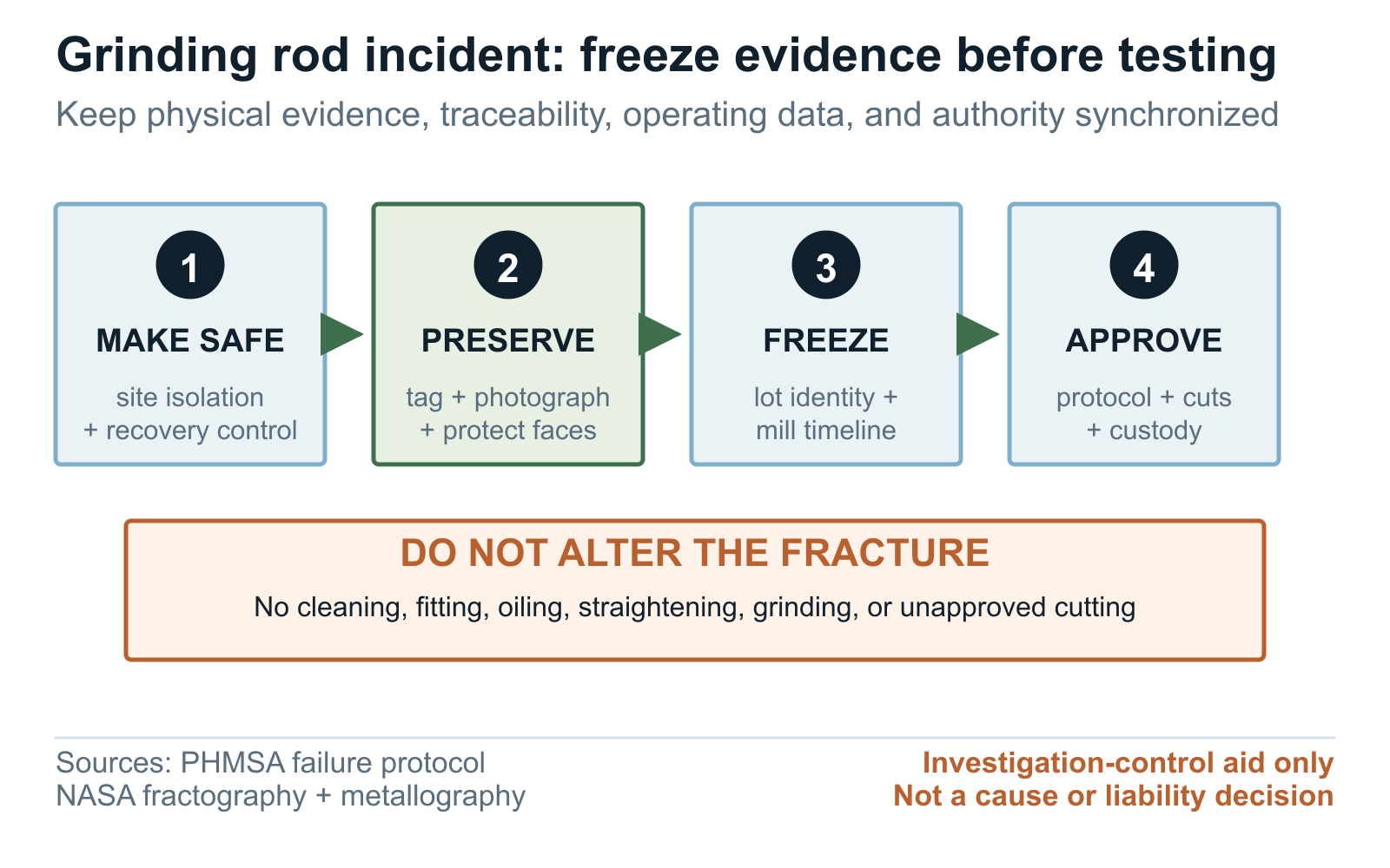
Preserve fracture surfaces in the as-recovered condition. Do not wire-brush, sandblast, grind, acid-clean, paint-mark on, oil, grease, or press the mating faces together. Those actions can remove deposits, smear surface features, create secondary marks, or contaminate later analysis.
Photograph each piece where found and again after recovery, using overview, mid-range, and close views with a scale and stable item identifier. Protect faces from contact with each other and ask the selected laboratory how they should be wrapped, dried, transported, and stored for the actual environment.
Retain more than the visibly failed piece. Keep a complete or representative set of fragments, a measured length on each side of the fracture where practical, bent or spalled rods, and an unused rod from the same supplier lot. If the charge contains legacy or mixed media, segregate and label those pieces rather than guessing their identity. Record any unavoidable cutting location and method before the cut; keep heat and mechanical damage away from the examination zone according to a laboratory-approved plan.
The PHMSA metallurgical protocol is written for line pipe, not grinding rods, but its evidence-handling principles are transferable: plan before destructive work, photograph before and after transport, preserve fracture surfaces, and maintain custody. NASA likewise describes fractography and metallography as complementary parts of a failure investigation. Neither source determines why a grinding rod failed or who is commercially responsible; they support the disciplined sequence used here.

Lot identity, mill timeline, and chain of custody
Create an incident register and chain of custody before samples leave the site. Give every rod, fragment, deposit sample, photograph set, document, and electronic log a unique identifier. Link that identifier to the supplier, purchase order, heat, process or heat-treatment lot, bundle, rod dimensions, charge date, recovery location, mass, condition, custodian, storage location, and every transfer. If a field is unknown, write unknown; do not backfill a convenient lot identity from memory.
Preserve the operating timeline around the event. Keep feed source and size, throughput, mill speed, power, water or slurry condition, and product target. Record charge mass and size mix, rod additions and removals, and worn-rod criteria. Include liner and discharge condition, starts and stops, and maintenance. Log abnormal noise or vibration, foreign objects, jams, overloads, and handling or charging incidents. State the time basis and missing data. This record does not assign responsibility to the plant. It gives supplier and buyer the same operating history to investigate.
Keep the product record beside the service record. Collect the accepted order, specification and edition, approved deviations, supplier quotation, mill test or inspection certificate, heat-treatment and inspection records promised by the order, bundle map, packing list, receipt inspection, storage history, and prior nonconformities. Confirm which rods were actually charged. A certificate for the correct grade cannot confirm that a recovered unmarked piece belongs to that heat, and a matching bundle label does not replace piece-level evidence when the charge was mixed.
Before destructive examination, circulate a short protocol to the buyer, supplier, laboratory, insurer or other authorized parties as required by the contract. State the questions, sample identities, permitted cleaning, cut map, tests, witness rights, data contactship, retained material, and change-control rule. Results at one stage should decide the next stage; a fixed list of every possible test can consume evidence without answering the incident question.
Break, bend, spall, or tangle?
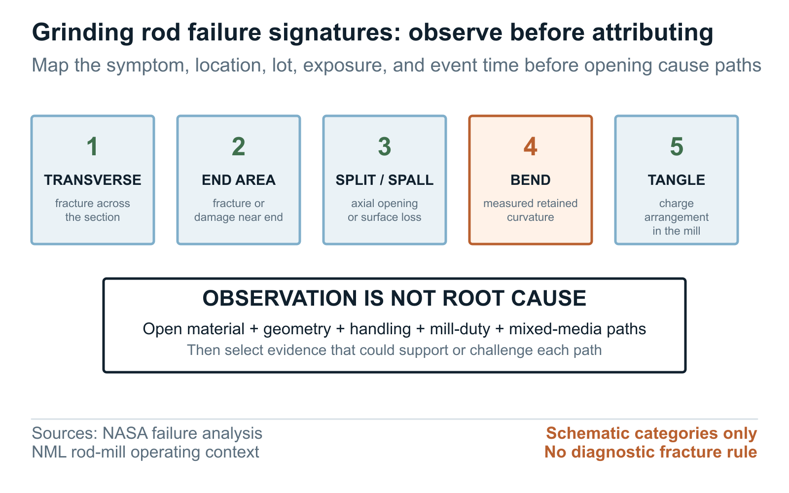
Use neutral observation terms first. A transverse fracture crosses the rod section. An end-area fracture falls within a buyer-defined distance from an end. A longitudinal split follows the rod axis. Spalling or shelling removes surface material. A bent rod retains measurable curvature after recovery, while a tangle describes the charge configuration. These labels organize evidence; they do not establish a root cause. They cannot alone prove brittle steel, low toughness, excessive hardness, improper heat treatment, poor straightness, bad mill operation, or impact damage.
Photograph the entire rod before focusing on the fracture. Record distance from each end, remaining length, diameter at several orientations, worn profile, end shape, marking, surface damage, corrosion or deposits, longitudinal seams or laps if visible, localized flattening, gouges, heat tint, and contact marks.
For a bent rod, establish a documented measurement support and span rather than judging curvature from a floor photograph. For a tangle, record the in-mill arrangement, rod length and diameter mix, broken and worn rods present, charge and discharge condition, and removal sequence.
A visual fracture surface can direct an experienced examiner toward an origin and propagation path, but field photographs rarely establish the complete mechanism. NASA notes that fractography can identify features such as initiation location, propagation direction, applied-stress information, and possible flaws; interpretation still depends on preserved surfaces, magnification, material condition, and service history. Ask the laboratory to distinguish observation, fracture mode, contributing mechanism, and root cause in separate report fields.
Rod-mill operation adds a specific boundary. The NML chapter describes rods working in roughly parallel alignment, removal of broken and worn rods, and tangling when rods become misaligned; it also discusses mill geometry, charge, speed, and deformation context. That source is operational guidance, not proof that any particular tangle or bend was caused by the mill rather than rod condition, handling, material, or combined contributors.
Use the grinding rod wear-pattern field guide to record end shape, rubbing, bow, and mixed charge profiles before fracture or metallurgical testing narrows the investigation.
| Observed condition | Record immediately | Contributor groups to investigate | Do not conclude from appearance alone |
|---|---|---|---|
| Transverse or angled fracture | Whole-rod and fracture photographs, origin area if visible, distance from ends, worn diameter, recovered mass, matching piece, lot identity, exposure, and event time. | Material and heat-treatment condition; surface or internal discontinuity; service impact or cyclic loading; handling damage; section and wear profile; mixed-media or operating event. | Brittle steel, insufficient toughness, excessive hardness, overload, fatigue, or supplier liability. |
| End-area fracture or damaged end | End geometry, cut or formed surface, local cracks, hardness-map location, contact damage, distance from end, handling and charging history, and orientation in the mill if known. | End manufacture and heat-treatment transition; local stress or contact; handling impact; rod length and mill clearances; worn or damaged charge condition. | An end-process defect or a mill-clearance problem without mapped evidence. |
| Longitudinal split, shell, or spall | Length and depth, circumferential position, adjacent surface, deposits, relation to markings, macro and micro sample map, and comparison-rod condition. | Surface or subsurface discontinuity; decarburization or heat-treatment condition; wear and corrosion interaction; contact damage; prior straightening or handling. | Seam, quench crack, inclusion, segregation, corrosion, or manufacturing nonconformity from one photograph. |
| Permanent bend or hook | Measurement method, support span, maximum deviation and location, diameter profile, end condition, gouges, temperature or handling events, charge mix, and whether deformation occurred before or during recovery. | Original straightness; plastic deformation in service; jam or tangle; lifting, transport, charging, or recovery damage; worn section; material and heat-treatment condition. | Low hardness, poor straightening, excessive mill load, or pre-delivery bend without a timeline and comparison evidence. |
| Rod-charge tangle | In-place photographs, affected area, rod length and diameter mix, broken and worn pieces, charge level, discharge condition, mill state, recent additions, and recovery sequence. | Misalignment; broken or deformed rods; mill geometry and clearances; charge practice; worn-rod removal; mixed sizes; operating or handling event. | One rod or one supplier caused the tangle merely because its piece was recovered nearby. |
A comparison-led sampling and test plan
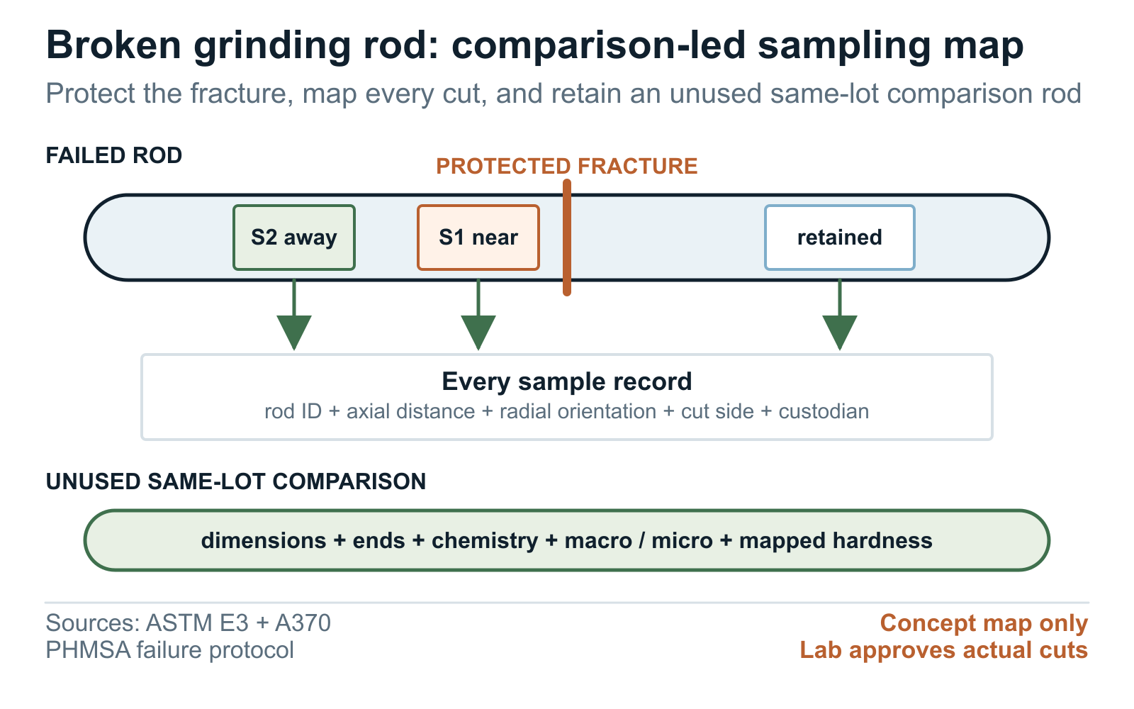
Ask the laboratory to design the cut map after reviewing the incident questions and as-received evidence. Protect at least one fracture face and enough adjacent material for fractography and near-origin work. Map every transverse and longitudinal section on a rod sketch with distance from the fracture and ends, radial orientation, surface condition, and cutting history. Preserve retained material for review or repeat work. A sample labeled only 'broken rod' cannot support a location-dependent hardness, microstructure, or discontinuity conclusion.
Choose comparison samples for a clear reason. An unused rod from the same implicated lot can help separate as-supplied features from service changes, but one rod may not represent a whole heat or process lot. A rod from a previously accepted lot can provide context only when grade, diameter, condition, sampling, and records are comparable. Mixed or unknown pieces should remain a separate identity class. Define how many rods, which positions, and which lots the commercial decision is intended to represent.
Stage the methods from least destructive to more destructive: as-received visual and dimensional documentation; suitable nondestructive examination when justified; fractography; chemistry; macrostructure; microstructure; hardness mapping; and mechanical testing only when it answers the agreed question and valid specimens can be obtained.
ASTM E3 emphasizes specimen location and orientation in metallography. ASTM E340 and E381 show that macroetching can reveal qualitative structure variation and discontinuities, while E381 also makes clear that purchaser and producer must agree the sections, preparation, method, and injurious conditions when it is a contractual inspection. [9][11][12]
Specify methods and reporting rather than asking for a generic 'metallurgical test.' For hardness, name the method and scale, surface preparation, radial and axial coordinates, spacing, number of readings, equipment verification, conversion policy, and uncertainty or repeatability information. For microstructure, name section orientation, etchant and method where appropriate, magnification, representative photomicrographs, and features to be assessed. For chemistry and mechanical properties, connect the specimen condition and location to the controlling order or investigation question.
| Sample or record | Purpose | Minimum mapping and protection | How far the result goes |
|---|---|---|---|
| Protected fracture pieces | Document fracture origin candidates, propagation features, deposits, surface condition, and fracture mode through qualified fractography. | Unique IDs, as-found and as-received photographs, face protection, recovery orientation, mating-piece identity, custody, and no unapproved cleaning or fitting. | Fracture appearance may support a mechanism; it doesn't alone establish material conformity, loading history, root cause, or liability. |
| Failed-rod transverse and longitudinal sections | Map hardness, macrostructure, microstructure, discontinuities, wear profile, and changes near and away from the apparent origin. | Rod sketch with axial distance, radial orientation, cut side, heat-affected exclusion, section preparation, method, and retained remainder. | A selected section represents its mapped location, not necessarily the whole rod, heat, process lot, or delivery. |
| Unused rod from the implicated lot | Compare as-supplied dimensions, straightness, end condition, chemistry, hardness profile, macrostructure, microstructure, and records. | Sealed identity from bundle or retained sample, full marking and dimensions, storage history, sampling plan, and chain of custody. | One comparison rod may reveal a difference but cannot define lot prevalence without an agreed statistical and contractual sampling basis. |
| Previously accepted comparison lot | Provide a contextual baseline for the same mill or specification when records and product condition are sufficiently comparable. | Supplier, grade, diameter, condition, heat and process route, sampling, service exposure, and accepted results documented side by side. | Historical acceptance is not a benchmark for every case, current-lot specification, or proof of superior future service. |
| Bent rod and straight comparison rods | Distinguish measured geometry, local plastic deformation, surface damage, worn section, and possible handling or mill-event evidence. | Defined support span and orientation, maximum deviation and location, diameter map, end condition, recovery method, and event timeline. | Recovered curvature does not reveal when or why the bend occurred without service, handling, and comparison evidence. |
| Operating, maintenance, and supplier records | Connect physical observations to charge history, mill events, supplier identity, promised process controls, inspection, and order requirements. | Original exports or controlled copies, synchronized timestamps, source owner, revision, missing-data statement, and approved deviations. | A record correlation is not causation, and an absent record isn't necessarily proof that an unrecorded event occurred. |
Hardness, microstructure, and mechanical results together
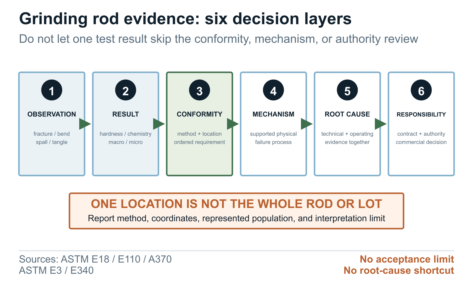
A hardness number needs coordinates and a method. ASTM E18 states that Rockwell hardness at a specific location may not represent the whole part. ASTM E110 adds that portable testers introduce variation, don't necessarily meet E10 or E18 requirements, and are sensitive to alignment and timing.
ISO 6508-1 defines Rockwell regular and superficial test methods for metallic materials, including applicable stationary and portable machines. Therefore compare like methods, scales, surface conditions, locations, verification states, and reporting rules; do not convert one field reading into a whole-rod hardness profile or toughness conclusion.
Map axial and radial trends against the ordered heat-treatment concept, but avoid a single ideal profile. Pugh and Ma's 1993 paper describes one historical development route in which uniformly increasing hardness could increase brittleness and high hardness could be associated with breakage problems; the authors investigated selective surface and core hardness.
That supplier-specific historical case supports balancing abrasion resistance and fracture resistance as an engineering question. It cannot confirm that a given modern rod is too hard, define an acceptable gradient, rank grades, or predict breakage in another mill.
Metallography and macroetching answer different questions. ASTM E3 and E407 support selecting, preparing, and etching mapped specimens for microscopic examination. ASTM E340 says macroetching can reveal qualitative heterogeneity, segregation patterns, hard or soft regions, and discontinuities, but chemical variation remains qualitative until measured by an appropriate method.
ASTM E381 warns that an indication has to be judged in relation to the part, so one acceptance rule cannot cover every case. Describe what was observed, where, by which method, and why it matters to the agreed requirement.
Interpret after-service mechanical results cautiously. ASTM A370 places material condition, sample frequency, location, orientation, and reporting in the product specification or order. It also notes that results after service can differ from specified or expected as-manufactured properties for reasons including environmental exposure, static or cyclic stress, mechanical damage, inhomogeneity, anisotropy, further processing, sampling limits, calibration uncertainty, and normal statistical variation. A failed-rod result should be compared with the accepted order, unused same-lot material, and service history before it becomes a conformity conclusion.
Competing causes and lot action
Build a contributor matrix that can hold more than one supported factor. Product-side paths can include specification mismatch, chemistry, heat-treatment profile, microstructure, discontinuity, dimensions, straightness, end condition, or traceability.
Plant-side paths can include charge condition, broken or worn rods left in service, mixed sizes, mill geometry or clearances, speed, feed, discharge, foreign objects, jam or abnormal event. Between them sit transport, storage, lifting, charging, recovery, and unrecorded mixing. Listing a path is not an accusation; each needs predicted evidence and a way to challenge it.
Use disconfirming evidence. If a supplier heat-treatment concern predicts a similar profile in unused rods from the same process lot, test an agreed sample rather than relying only on the deformed service piece. If a tangle hypothesis depends on length mix, broken rods, charge condition, or discharge interference, examine the full charge and logs rather than only the selected fracture. If handling damage is proposed, compare contact marks, bend location, lifting method, receipt inspection, and photographs across the custody timeline.
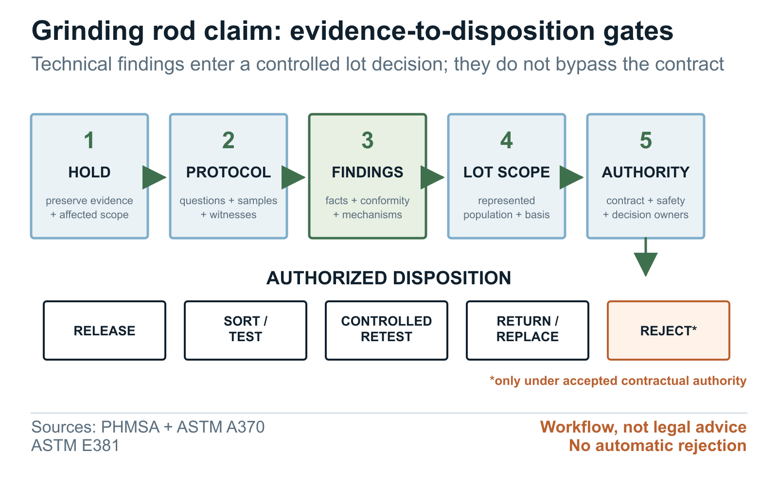
Separate the technical finding from lot prevalence. Even a well-supported mechanism in one rod may not establish how many rods are affected. Define which lots or pieces the finding applies to and check the contractual sampling rule before releasing or rejecting material. The purchaser may hold the lot, inspect more pieces, sort it, test retained samples, or run a controlled trial while the commercial claim remains open. Name the people responsible for safety and approval.
Use review steps: preserve and hold; approve the examination protocol; review observed facts and specification conformity; assess supported mechanisms and contributor evidence; decide lot scope; then authorize release, conditional use, sorting, controlled retest, return, replacement, or rejection under the accepted contract. Preserve raw data, images, remnants, calculations, dissenting observations, and deviation approvals. A quick supplier credit can close a commercial issue without proving root cause; a technically credible report can still leave contractual responsibility unresolved.
| Contributor path | Evidence that may support or challenge it | Comparison or control | How the buyer will use it |
|---|---|---|---|
| Material, steelmaking, or heat-treatment route | Accepted specification and deviations; traceable chemistry; mapped hardness; macro and micro observations; discontinuity evidence; fracture examination; supplier process and inspection records promised by the order. | Unused same-lot rods, mapped sections away from the failure, prior comparable lot where valid, and laboratory method controls. | One failed location cannot confirm whole-lot nonconformity, prevalence, or liability. |
| Dimensions, straightness, ends, and wear profile | Receipt and recovered measurements; defined straightness method; diameter map; length; end condition; local damage; wear profile; approved tolerances; mill clearance context. | Unused same-lot rod, documented receipt inspection, straight rods from the charge, and measurements using the same method. | Recovered geometry may include service or recovery deformation and must be linked to the event timeline. |
| Transport, storage, lifting, charging, or recovery | Packing and receipt records; storage supports; lifting points; impact or gouge marks; charging and recovery method; time-stamped photographs; custodian statements and equipment records. | Other rods handled in the same event, pre-charge images, unused stock, and the damage location predicted by the handling hypothesis. | A missing handling record is a data gap, not automatic proof of mishandling. |
| Mill operation and rod-charge condition | Speed, power, feed, water or slurry, charge mass and mix, additions and removals, broken and worn rods, liners, discharge, starts and stops, abnormal events, foreign objects, and tangle arrangement. | Stable periods before and after, other mills where sufficiently comparable, full-charge inspection, and synchronized process data. | An operating correlation does not excuse product nonconformity or prove that operation caused the failure. |
| Mixed, legacy, or unidentified media | Piece and bundle marks, chemistry where appropriate, dimensions, hardness and structure differences, charge records, storage segregation, and recovery location. | Known supplier lots and unused retained rods; treat unknown pieces as a separate identity class. | Do not assign an unidentified fragment to the newest delivery or a named supplier without traceable evidence. |
A fact-led incident package for the supplier
A clear supplier notice separates observed facts, open hypotheses, requested records, proposed examination, temporary containment, and requested commercial response. State which rods and lots are on hold, but avoid phrases such as 'defective heat treatment' or 'supplier-caused brittle fracture' until supported by the accepted specification and evidence. Ask the supplier to preserve corresponding production, heat-treatment, straightening, inspection, bundle, and retained-sample records that the order entitles the purchaser to review.
Attach controlled files: incident chronology, recovery map, photo index, rod and fragment register, custody log, mill operating extract, maintenance and handling events, order and deviation hierarchy, certificate and traceability map, proposed sample plan, laboratory scope, and open-question list. Mark missing fields. If the parties disagree, record the disagreement and preserve sufficient material for witnessed or independent work rather than consuming every sample in the first examination.
Define the requested outcome and deadline without predetermining cause. The buyer may ask for acknowledgement, record preservation, supplier technical representative, protocol comments, replacement or containment proposal, and a reservation of contractual rights. Final choices—continued hold, release, sort and inspect, expanded sampling, controlled mill retest, return, replacement, price adjustment, or rejection—remain subject to site safety, the accepted contract, evidence, and authorized decision makers.
The template leaves values in brackets because incident facts and contract terms belong to the buyer. It cannot add a warranty, admission, rejection right, test acceptance limit, or legal position. For a consequential failure, injury, insurer matter, or likely dispute, obtain competent metallurgical, operational, commercial, and legal review before destructive testing or formal attribution.
Subject: Grinding rod incident notice — [site and mill]
Incident: [date/time, mill, operating state, safe shutdown or recovery status]
Observed condition: [breakage, bend, split, spalling, tangling, other] described without assigning cause
Material on hold: [supplier, PO, size, grade/standard, heat, heat-treatment lot, bundle, quantity]
Traceability: [confirmed piece/bundle link, mixed charge, unidentified material, missing records]
Records and samples preserved: [tagged rods/fragments, as-found photographs, protected fracture faces, unused same-lot rod, custody log]
Do not alter: [no cleaning, straightening, cutting, grinding, destructive testing, or disposal before protocol approval]
Operating record: [feed, throughput, speed, power, slurry/water, charge, liners/discharge, starts/stops, abnormal events]
Order records: [accepted specification, deviations, certificate, heat-treatment and inspection records, bundle map]
Working hypotheses: [material, heat treatment, discontinuity, dimensions, handling, mill duty, mixed media]
Examination plan: [visual/dimensional record, NDE if justified, fractography, chemistry, macro/microstructure, hardness map]
Sample map: [fracture area, section away from origin, unused same-lot rod, comparison lot where valid]
Supplier response due: [date, technical contact, record preservation, protocol comments, containment]
Contacts and responsibilities: [site safety, buyer technical, procurement, supplier, laboratory]
Lot action: [continue hold, release unaffected material, inspect, retest, return, replace, or reject under the accepted contract]
This notice preserves the facts and original records. It doesn't assign root cause, warranty, liability, or lot prevalence.Questions buyers ask
What should a buyer do immediately after a grinding rod breaks?
Make the mill and recovery work safe under site procedures, name an investigation owner, isolate the implicated and unidentified material, photograph and tag every piece, preserve the fracture faces without cleaning or fitting them together, retain an unused same-lot comparison rod, and preserve the operating, maintenance, handling, order, and traceability records before destructive testing.
Does a brittle-looking grinding rod fracture prove that the rod was too hard?
No. Appearance can guide qualified fractography, but hardness needs a named method, scale, mapped location, surface condition, and comparison basis. The investigation must also consider microstructure, discontinuities, dimensions, service loading, wear, mill events, handling, traceability, and after-service changes before assigning a mechanism or cause.
Can one portable hardness reading prove a grinding rod lot is defective?
No. ASTM E110 warns that portable testing introduces variation and that one location may not represent the whole part. A lot decision needs an agreed method, verification, axial and radial map, representative same-lot sampling, accepted specification, raw results, and interpretation of service condition and uncertainty.
What samples should be retained after broken grinding rods are recovered?
Retain protected fracture pieces, adjacent rod lengths, bent or spalled pieces, deposits when relevant, an unused rod from the implicated lot, and—if valid—a documented comparison lot. Record the rod, cut location, orientation, lot, custodian, and cut history for every sample, and keep unused remnants for review.
What causes grinding rods to bend or tangle in a rod mill?
Bending and tangling can have multiple or combined contributors, including rod condition, wear, breaks, length and diameter mix, charge practice, mill geometry or discharge condition, operating events, foreign objects, and transport, charging, or recovery damage. The recovered shape or nearby fragment alone cannot determine which path applies.
What should be included in a grinding rod supplier claim file?
Include a neutral incident chronology, material-on-hold scope, traceability map, rod and fragment register, protected photographs, custody log, operating and maintenance timeline, handling events, accepted order and deviations, certificate and promised process records, agreed sample and test protocol, raw results, retained material, open hypotheses, requested response, and authorized disposition options.
RFQ checklist
- Site safety, isolation, recovery, lifting, confined-space, hot-work, and evidence-preservation owners named
- Incident number, site, mill, compartment, date, time, operating state, alarm, shutdown, and recovery sequence
- Every rod, fragment, deposit sample, photograph set, document, and data export assigned a stable identifier
- As-found, in-mill, recovery, as-received, whole-rod, fracture, end, bend, spall, and tangle photographs indexed
- Fracture faces protected from cleaning, contact, fitting, oil, grease, paint marking, grinding, and unapproved cutting
- Supplier, purchase order, grade, standard edition, heat, process or heat-treatment lot, bundle, and piece identity status
- Implicated, mixed, legacy, and unidentified rods segregated into clear administrative-hold classes
- Unused same-lot comparison rod and sufficient failed-rod remnants retained under documented custody
- Feed, throughput, speed, power, water or slurry, product target, charge mass, size mix, and additions synchronized
- Broken and worn rod removals, liner and discharge state, starts, stops, noise, vibration, jam, overload, and foreign objects
- Transport, packing, receipt, storage supports, lifting, charging, straightening, and recovery events preserved
- Accepted order, specification hierarchy, deviations, quotation, certificate, inspection, heat-treatment, and bundle records
- Neutral symptom classification and rod map completed without assigning root cause or liability
- Laboratory selected for relevant fractography, metallography, hardness, chemical, and steel-product capability
- Written protocol fixes questions, sample identities, cleaning, cuts, methods, witnesses, raw data, remnants, and changes
- Hardness method, scale, equipment verification, surface preparation, axial and radial coordinates, and conversions controlled
- Macro and micro sections mapped by location and orientation with etching method and representative images
- Mechanical-test specimen condition, location, orientation, method, and controlling specification defined before testing
- Contributor matrix includes product, handling, operation, geometry, mixed-media, supporting, and disconfirming evidence
- Lot covered or population and contractual sampling basis stated separately from the single-rod mechanism
- Temporary containment, expanded inspection, controlled retest, stop rules, release, return, replacement, and rejection authority
- Supplier notice separates facts, open hypotheses, requested records, proposed protocol, response deadline, and reservation
- Raw data, original images, calculations, missing fields, deviations, dissenting observations, retained material, and approvals archived
- Technical findings, product conformity, root cause, lot prevalence, warranty, commercial remedy, and legal responsibility reported separately
References
- Metallurgical Laboratory Failure Examination Protocol
- Microstructural Analysis: Fractography and Metallography
- Comminution — Theory and Plant Practice, Chapter 6
- Heat Treated Grinding Rods
- ASTM A370-26 Standard Test Methods and Definitions for Mechanical Testing of Steel Products
- ASTM E18-25 Standard Test Methods for Rockwell Hardness of Metallic Materials
- ASTM E110-14(2023) Standard Test Method for Rockwell and Brinell Hardness by Portable Hardness Testers
- ISO 6508-1:2023 Metallic materials — Rockwell hardness test — Part 1: Test method
- ASTM E3-26 Standard Guide for Preparation of Metallographic Specimens
- ASTM E407-23 Standard Practice for Microetching Metals and Alloys
- ASTM E340-23 Standard Practice for Macroetching Metals and Alloys
- ASTM E381-22 Standard Method of Macroetch Testing Steel Bars, Billets, Blooms, and Forgings
Inquiry support
Working from a part drawing?
Send the drawing or RFQ with the grade, size, condition, processing, inspection, quantity, and destination. We can flag open points before quotation.